Table of Contents
Advertisement
Quick Links
Advertisement
Table of Contents

Related Manuals for IXIA FireStorm ONE


Summary of Contents for IXIA FireStorm ONE
- Page 1 FireStorm ONE Installation Guide Release 8.0.1, Mar. 2016...
- Page 2 DFARS 252.227-7013 and FAR 52.227-19. Ixia, the Ixia logo, and all Ixia brand names and product names in this document are either trademarks or registered trademarks of Ixia in the United States and/or other countries. All other trademarks belong to their respective owners.
-
Page 3: Table Of Contents
Strike Center......ii Support......ii Documentation Feedback......iii Product Overview FireStorm ONE Overview......1 FireStorm ONE Front View......1 Control Center Overview......2 Getting Started Getting Started Overview......7 Task 1: Installing the BreakingPoint Device......8 Task 2: Configuring the BreakingPoint Device......8 Task 3: Establishing a BreakingPoint Session...... - Page 4 Shipping Package Contents Overview......29 Installation Overview......29 Mounting the Appliance into an Equipment Rack......30 Powering the System......33 Connecting a Device Under Test to the FireStorm ONE......34 System Configuration Initial Configuration......35 Accessing the Control Center Accessing the Control Center......39 Frequently Asked Questions Account Questions......
- Page 5 Table of Contents Appendix Hardware Specifications......I Software Specifications......II Light-Emitting Diodes......II Shipping Container Contents......III CLI Commands......IV FireStorm ONE Installation Guide...
-
Page 6: About This Guide
Organization This guide is organized into the following sections: • About this Guide • Product Overview • Site and Safety Requirements • FireStorm ONE Installation • System Configuration • Accessing the Control Center • Frequently Asked Questions • Appendix • Index... -
Page 7: Related Documentation
Related Documentation Table I-2 on page ii lists all the documentation related to the FireStorm ONE. All documentation can be accessed through the Documentation area of Strike Center. Table I-2: Related Documentation Documentation... -
Page 8: Documentation Feedback
• Customer Number – Located on the Customer Support Agreement and on the shipping invoice for the FireStorm ONE. • Serial Number – Located on the shipping invoice for the FireStorm ONE. • Firmware Versions – Located from the Help Menu in the Control Center (select Help > About). - Page 9 Documentation Feedback FireStorm ONE Installation Guide BreakingPoint Systems Inc. ©2005-2016...
-
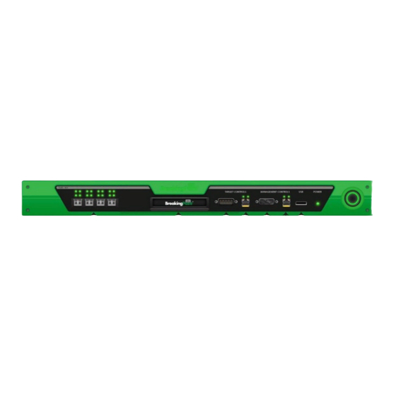
Page 10: Product Overview
BreakingPoint Systems has developed a system that measures and hardens the resiliency of every component of your critical infrastructure against potentially crippling attacks and peak application traffic: the FireStorm ONE. It is a 1U, rack-mountable system that can accurately recreate a live network environment. -
Page 11: Control Center Overview
FireStorm ONE is connected to an improper power supply configuration. When connecting power to your FireStorm ONE, be sure to use only the power supply that was shipped with our FireStorm ONE appliance. Target Control Serial Port Used to manage and configure settings for the DUT. - Page 12 Additionally, you must have the host address that has been set for the BPS Management Port and the Control Center login information. Note: The chassis must already be installed and configured before the Control Center can be accessed. FireStorm ONE Installation Guide BreakingPoint Systems Inc. ©2005-2016...
- Page 13 Note: The system allows three invalid logins. If invalid login information is entered on the fourth attempt, the login window will lock the user out. Users must refresh their browser to unlock their accounts. FireStorm ONE Installation Guide BreakingPoint Systems Inc. ©2005-2016...
- Page 14 Provides access to the Device Status area so that you can reserve ports while no tests are running or the Real Time Statistics screen if there is a running test. Navigational Buttons Provides access to areas within the user interface. FireStorm ONE Installation Guide BreakingPoint Systems Inc. ©2005-2016...
- Page 15 Control Center Overview FireStorm ONE Installation Guide BreakingPoint Systems Inc. ©2005-2016...
-
Page 16: Getting Started
• Task 10: Creating a Test Getting Started Overview Welcome to the Getting Started section of the FireStorm ONE Installation Guide. This section will provide an overview of the tasks you must complete in order to install and configure the BreakingPoint device, as well as explain how to set up your test environment within the BreakingPoint Control Center. -
Page 17: Task 1: Installing The Breakingpoint Device
Figure 2-1: Network Information Box Telnet This section will describe how to configure the host address, netmask, and gateway for the BreakingPoint device using either a telnet client or a text console. FireStorm ONE Installation Guide BreakingPoint Systems Inc. ©2005-2016... - Page 18 2. Connect to the BPS Management serial port using the following settings: • Baud Rate: 115200 bps • Data Bits: 8 • Parity: None • Stop Bits: 1 • Flow Control: None FireStorm ONE Installation Guide BreakingPoint Systems Inc. ©2005-2016...
-
Page 19: Task 3: Establishing A Breakingpoint Session
1. Open a web browser. 2. In the URL field, type the IP address or hostname of the Ixia chassis where the Ixia Web App server components are installed, followed by the port number that the Ixia Web App server is listening on (the default is 8080), and then press Enter. -
Page 20: Task 4: Accessing The Breakingpoint Control Center
2. Select Tools > Options from the BreakingPoint Control Center Menu bar. 3. Select the Content button located at the top of the window. 4. Click the Enable JavaScript option. 5. Click the OK button to exit the Options window. FireStorm ONE Installation Guide BreakingPoint Systems Inc. ©2005-2016... - Page 21 The BreakingPoint Control Center is divided into two main areas: the BreakingPoint Control Center Menu bar and the navigational buttons. See Figure 2-2 on page 13 for a tour of the interface. FireStorm ONE Installation Guide BreakingPoint Systems Inc. ©2005-2016...
-
Page 22: Task 5:Creating A User Account
Only admin users can create user accounts or edit all the properties of a user account. If you are a non-admin user, the only change you can make to your own account is to change your password. To create or edit a user account: Log in with an admin account. FireStorm ONE Installation Guide BreakingPoint Systems Inc. ©2005-2016... -
Page 23: Task 6: Setting The Time And Date
Task 6: Setting the Time and Date To set the system time and day, go to the System Settings tab of the Ixia Administration page. The controls on this window set the time and date on the chassis. The system time and date appears in test results and system logs. -
Page 24: Task 7: Creating A Device Under Test Profile
Profiles in the user guide. Note: The BreakingPoint device provides a default DUT Profile called BreakingPoint Default. This DUT Profile cannot be modified or deleted; however, it can be cloned and customized for your device. FireStorm ONE Installation Guide BreakingPoint Systems Inc. ©2005-2016... - Page 25 8. Enable or disable any global commands from the Global Commands list. Note: All cloned DUT Profiles will inherit the active global commands from its parent DUT Profile. For more information on commands, see the section Commands in the user guide. FireStorm ONE Installation Guide BreakingPoint Systems Inc. ©2005-2016...
-
Page 26: Task 8: Creating A Network Neighborhood
2. Adding a domain to the Network Neighborhood. 3. Defining the subnet for the domain. 4. Adding additional interfaces to the Network Neighborhood (for two-blade chassis). Creating a Network Neighborhood This section describes how to create a Network Neighborhood. FireStorm ONE Installation Guide BreakingPoint Systems Inc. ©2005-2016... - Page 27 This section describes how to add a subnet to a non-VLAN tagging subnet on a non-external interface. For information on external device addressing or VLAN-enabled addressing, see the section External Interface Addressing or Defining a VLAN-Enabled Subnet in the user guide. FireStorm ONE Installation Guide BreakingPoint Systems Inc. ©2005-2016...
- Page 28 0-255. To assign an IPv6 address, use the format x:x:x:x where x is a valid hexadecimal value. 12. Click the Type dropdown button. 13. Do one of the following: FireStorm ONE Installation Guide BreakingPoint Systems Inc. ©2005-2016...
- Page 29 Once you have added the interface to the Network Neighborhood, you can add subnets in the usual way. For more information on defining subnets, see the section Defining a Subnet on page FireStorm ONE Installation Guide BreakingPoint Systems Inc. ©2005-2016...
-
Page 30: Task 9: Making Port Reservations
Device Options screen, and manually remap the ports. Note: Only reserved ports will can be mapped to interfaces. To reserve ports on an unreserved blade: 1. Select Control Center > Device Status from the BreakingPoint Control Center Menu bar. FireStorm ONE Installation Guide BreakingPoint Systems Inc. ©2005-2016... - Page 31 1. Select Control Center > Device Status from the BreakingPoint Control Center Menu bar. 2. Click the Active Group that you would like to use from the dropdown menu. 3. Right-click on the slot that has the ports you would like to reserve or unreserve. FireStorm ONE Installation Guide BreakingPoint Systems Inc. ©2005-2016...
-
Page 32: Task 10: Creating A Test
Neighborhood. Once you have made your changes, click the Return button to go back to the DUT and Network Neighborhood selection screen. For more information on Network Neighborhoods, see the section Task 8: Creating a Network Neighborhood on page FireStorm ONE Installation Guide BreakingPoint Systems Inc. ©2005-2016... - Page 33 11. Click the Save As button. 12. Enter a name for the test in the Name field. 13. Click Save and Run from the Test Quick Steps menu to run the test. FireStorm ONE Installation Guide BreakingPoint Systems Inc. ©2005-2016...
-
Page 34: Site And Safety Regulations
Ventilation Requirements The FireStorm ONE appliance contains a fan tray that pulls in cool air from the right side of the appliance and exhausts hot air on the left. There must be at least 3 inches of clearance at all of the ventilation openings to ensure that the appliance is properly ventilated. -
Page 35: Safety Recommendations
This section covers the safety recommendations that you must read before installing or operating the FireStorm ONE. Keep in mind that any electronic equipment – like the appliance – can create a dangerous environment for employees and surrounding equipment if it is installed improperly. - Page 36 • Do not touch uninsulated wires or terminals unless all cables and connections have been disconnected from the appliance. • Do not remove the fan tray while the FireStorm ONE is powered on. Power the system off and wait until the fans have stopped running before removing the fan tray from the system.
-
Page 37: Installation Guide
2. Power on the system. For more information on powering on the system, see the section Powering the System on page 3. Connect the device under test to the FireStorm ONE. For more information on connecting a device under test to the FireStorm ONE, see the section... -
Page 38: Mounting The Appliance Into An Equipment Rack
1.75 inches and is comprised of three mounting holes. If you look at the rack’s mounting rails, you will notice small markers that indicate each rack unit. For the FireStorm ONE appliance, you will need 1 RU of rackspace. - Page 39 3. (Optional) If you decide to use the extension brackets: Attach the extension bracket to the body of the appliance first. Next, attach the rack-mount bracket to the extension bracket. FireStorm ONE Installation Guide BreakingPoint Systems Inc. ©2005-2016...
- Page 40 Mounting the Appliance Use the following instructions to mount the FireStorm ONE appliance to the equipment rack from the front. This process requires at least three people. To install the FireStorm ONE to an equipment rack: 1.
-
Page 41: Powering The System
11. Connect the supplied Ethernet cable from the management port to your PC or network hub. You may optionally connect the supplied serial cable to the DB9 serial port on the FireStorm ONE appliance for performing some management functions. -
Page 42: Connecting A Device Under Test To The Firestorm One
Connecting a Device Under Test to the FireStorm ONE After mounting and configuring the FireStorm ONE, you can connect your device(s) under test to the system. Note: The system can be powered on when you connect the device under test to the FireStorm ONE. -
Page 43: System Configuration
Initial Configuration During an initial configuration, you will set up the IP address, netmask, and gateway for the FireStorm ONE. Additionally, during this process, you will create a user account that will be used to log into the Control Center. - Page 44 Administration area of the Control Center. Text Console To configure the FireStorm ONE through a text console, the appliance must be connected to a computer through the BPS Management serial port. To configure the network settings via text console: 1.
- Page 45 The system will disconnect while the new network settings are applied and the account is created. Note: Document the host address and user account information configured for the FireStorm ONE. You will need this information to access and log into the Control Center. Once you have logged in, you can create additional user accounts, if necessary, through the Administration area of the Control Center.
- Page 46 Initial Configuration FireStorm ONE Installation Guide BreakingPoint Systems Inc. ©2005-2016...
-
Page 47: Accessing The Control Center
• Accessing the Control Center Accessing the Control Center You can access the Control Center after you have configured the FireStorm ONE. When you access the Control Center, the first page that launches is the BreakingPoint Systems main page. From the main page, you can download the TCL shell, access Strike Center, view the online Help, find BreakingPoint Systems contact information, and launch the Control Center user interface. - Page 48 Accessing the Control Center FireStorm ONE Installation Guide BreakingPoint Systems Inc. ©2005-2016...
-
Page 49: Frequently Asked Questions
Answer: If you edit the Network Neighborhood selected for your test, you can select “Host” as the type for the domain. This will allot one MAC address per host; selecting “Virtual Router” will use one MAC address total for all traffic from that subnet. FireStorm ONE Installation Guide BreakingPoint Systems Inc. ©2005-2015... -
Page 50: Bandwidth Questions
Question: How do I determine how much bandwidth each test component is using? Answer: The system has a test status verification feature that tells you whether or not the test components have exceeded the maximum allowed bandwidth for each interface. FireStorm ONE Installation Guide BreakingPoint Systems Inc. ©2005-2015... -
Page 51: System Questions
System Questions Question: What are the power requirements for the FireStorm ONE? Answer: The following are the power requirements for the FireStorm ONE: 100-240 VAC, 4 A at 50-60 Hz, and a maximum power consumption of 400 Watts. Question: What is the manufacturer MAC address for the BPS Management port? -
Page 52: Troubleshooting Questions
After you have reseated the fan tray, power the system on. If this does not resolve your issue, please contact BreakingPoint Support. FireStorm ONE Installation Guide BreakingPoint Systems Inc. ©2005-2015... -
Page 53: Update Questions
Question: Will ATI Updates update my existing Strike Lists with the latest Strikes? Answer: All ATI Updates will populate Smart Strike Lists with current strikes. Standard Strike Lists must be manually updated after applying any ATI upgrade. FireStorm ONE Installation Guide BreakingPoint Systems Inc. ©2005-2015... - Page 54 Update Questions FireStorm ONE Installation Guide BreakingPoint Systems Inc. ©2005-2015...
-
Page 55: Hardware Specifications
Appendix This section details the hardware and software specifications for the FireStorm ONE. Hardware Specifications Table A-1 on page I details the hardware specifications for the FireStorm ONE. Table A-1: Hardware Specifications Hardware Component Specification Model FireStorm ONE Dimensions Height: 7 inches (17.8 cm) Width: 17.4 inches (44.2 cm) -
Page 56: Software Specifications
Serial Client Serial client running 115200/8/n/l/none Light-Emitting Diodes The light-emitting diodes (LEDs) status indicators are located on the front of the FireStorm ONE. Table A-3 on page II for descriptions of each LED and what each LED color represents. Table A-3: LED Statuses... -
Page 57: Shipping Container Contents
Table A-4: Shipping Container Quantity Item 1 – FireStorm ONE Appliance 1 – AC input cable 2 – 10’ DB9 serial cables 2 – 10’ CAT6 Ethernet cables 1 – Hard Drive Module 1 –... -
Page 58: Cli Commands
HTTP Off: <true> turns port 80 updateUser Modify a user account updateUser joe -name Joseph Smith -email joeS@email.com uptime Display the system’s uptime uptime userInfo Query a user’s information userInfo joe version Display the software version version FireStorm ONE Installation Guide BreakingPoint Systems Inc. ©2005-2016... - Page 59 Index Adobe Flash Player altitude BPS Management Ethernet Port BPS Management Serial Port BreakingPoint Control Center CE Mark Certification Class 1 lasers Connection Type Control Center Data Ports degradation Device Selection Device Status DHCP Enable/Disable Diagnostics File DUT Profile EIA-310-C EIA-310C Electrostatic Discharge equipment rack...
- Page 60 Index Gateway gateway Gateway IP Address Hard drive tray Host Host Address host address humidity initial configuration JavaScript Locked Account login ID MAC Address Management COM Port Maximum IP Address Menu Bar Minimum IP Address Navigational Buttons...
- Page 61 Index Netmask netmask Network IP Address Network Neighborhood network settings non-operating environment operating environment optical transceivers password port notes port reservations power cable Preload for slower connections Reset Password Router IP Address SFP optical receivers Strike Center Account Password Subnet Target Control COM/Serial Port Target Control Ethernet Port telnet...
- Page 62 Index test interface text console Time and Date UL-60950-1 USB Port Use Address Range Virtual Router...
Need help?
Do you have a question about the FireStorm ONE and is the answer not in the manual?
Questions and answers