Table of Contents
Advertisement
Advertisement
Table of Contents

Related Manuals for IXIA BreakingPoint 20


Summary of Contents for IXIA BreakingPoint 20
- Page 1 BreakingPoint 20 Installation Guide Release 3.4, Jan. 2015...
- Page 2 DFARS 252.227-7013 and FAR 52.227-19. Ixia, the Ixia logo, and all Ixia brand names and product names in this document are either trademarks or registered trademarks of Ixia in the United States and/or other countries. All other trademarks belong to their respective owners.
- Page 3 Outer Ring Road, Varthur Hobli Kadubeesanahalli Village Bangalore East Taluk Bangalore-560 037, Karnataka, India +91 80 42862600 For viewing the FAQs related to the product, go to Ixia Technical Support Online: https://ebsoprod.ixiacom.com/OA_HTML/jtflogin.jsp BreakingPoint 20 Installation Guide, Release 3.4...
- Page 4 BreakingPoint 20 Installation Guide, Release 3.4...
-
Page 5: Table Of Contents
Strike Center......ii Support......ii Documentation Feedback......iii Product Overview BreakingPoint 20 Overview......1 BreakingPoint 20 Hardware Overview......1 Control Center Overview......3 Getting Started Getting Started Overview......7 Task 1: Installing the BreakingPoint Device......8 Task 2: Configuring the BreakingPoint Device......8 Task 3: Establishing a BreakingPoint Session...... - Page 6 Safety Regulations......28 Installation Guide Shipping Package Contents Overview......29 Installation Overview......29 Powering the System......32 Connecting a Device Under Test to the BreakingPoint 20......33 System Configuration Initial Configuration......35 Factory Revert......36 Accessing the Control Center Accessing the Control Center......37 Frequently Asked Questions Account Questions......
- Page 7 Table of Contents Appendix Hardware Specifications......I Software Specifications......II Light-Emitting Diodes......II Shipping Container Contents......III CLI Commands......IV BreakingPoint 20 Installation Guide...
-
Page 8: About This Guide
This guide uses the conventions listed in Table I-1: Document Conventions Convention Description Example Bolded text Commands, keywords, or buttons Press the Enter key. User input Type GET in the Method Courier font Request field. BreakingPoint BreakingPoint 20 Installation Guide BreakingPoint Systems Inc. © 2005-2015... -
Page 9: Related Documentation
Related Documentation Table I-2 on page ii lists all the documentation related to the BreakingPoint 20. All documentation can be accessed through the Documentation area of Strike Center. Table I-2: Related Documentation Documentation... -
Page 10: Documentation Feedback
• Customer Number – Located on the Customer Support Agreement and on the shipping invoice for the BreakingPoint 20. • Serial Number – Located on the shipping invoice for the BreakingPoint 20. • Software Versions – Located from the Help Menu in the Control Center (select Help > About). - Page 11 Documentation Feedback BreakingPoint BreakingPoint 20 Installation Guide iv BreakingPoint Systems Inc. © 2005-2015...
-
Page 12: Product Overview
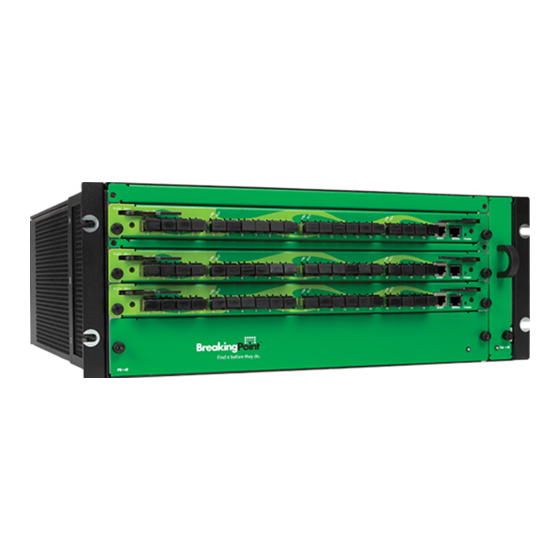
The BreakingPoint 20 consists of the chassis, and the user interface called the Control Center. Both components work together to create a comprehensive and user-friendly test solution for all network devices. - Page 13 Front-view of the BreakingPoint 20 Figure 1-2 on page 2 illustrates the front of the BreakingPoint 20. Locate the corresponding callout in the table below for more information about each component. Figure 1-2: BreakingPoint 20 Front View Table 1-1: BreakingPoint 20 Front View...
-
Page 14: Control Center Overview
BNC Interfaces Interfaces that are used to connect multiple chassis together (for clock I/O and trigger I/O) Power Switch Power breaker switch for the BreakingPoint 20 Power Inlet Power inlet for the BreakingPoint 20 Control Center Overview The Control Center is a Web-based user interface where the testing environment can be created, tests can be run, and reports can be viewed. - Page 15 Additionally, you must have the host address that has been set for the BPS Management Port and the Control Center login information. Note: The chassis must already be installed and configured before the Control Center can be accessed. BreakingPoint BreakingPoint 20 Installation Guide 4 BreakingPoint Systems Inc. © 2005-2015...
- Page 16 Note: The system allows three invalid logins. If invalid login information is entered on the fourth attempt, the login window will lock the user out. Users must refresh their browser to unlock their accounts. BreakingPoint BreakingPoint 20 Installation Guide 5 BreakingPoint Systems Inc. © 2005-2015...
- Page 17 Real Time Statistics screen if there is a running test. Navigational Buttons Provides access to areas within the user interface. BreakingPoint BreakingPoint 20 Installation Guide 6 BreakingPoint Systems Inc. © 2005-2015...
-
Page 18: Getting Started
• Task 10: Creating a Test Getting Started Overview Welcome to the Getting Started section of the BreakingPoint 20 Installation Guide. This section will provide an overview of the tasks you must complete in order to install and configure the BreakingPoint device, as well as explain how to set up your test environment within the BreakingPoint Control Center. -
Page 19: Task 1: Installing The Breakingpoint Device
Figure 2-1: Network Information Box Telnet This section will describe how to configure the host address, netmask, and gateway for the BreakingPoint device using either a telnet client or a text console. BreakingPoint 20 Installation Guide BreakingPoint Systems Inc. © 2005-2015... - Page 20 2. Connect to the BPS Management serial port using the following settings: • Baud Rate: 115200 bps • Data Bits: 8 • Parity: None • Stop Bits: 1 • Flow Control: None BreakingPoint 20 Installation Guide BreakingPoint Systems Inc. © 2005-2015...
-
Page 21: Task 3: Establishing A Breakingpoint Session
1. Open a web browser. 2. In the URL field, type the IP address or hostname of the Ixia chassis where the Ixia Web App server components are installed, followed by the port number that the Ixia Web App server is listening on (the default is 8080), and then press Enter. -
Page 22: Task 4: Accessing The Breakingpoint Control Center
2. Select Tools > Options from the BreakingPoint Control Center Menu bar. 3. Select the Content button located at the top of the window. 4. Click the Enable JavaScript option. 5. Click the OK button to exit the Options window. BreakingPoint 20 Installation Guide BreakingPoint Systems Inc. © 2005-2015... - Page 23 The BreakingPoint Control Center is divided into two main areas: the BreakingPoint Control Center Menu bar and the navigational buttons. See Figure 2-2 on page 13 for a tour of the interface. BreakingPoint 20 Installation Guide BreakingPoint Systems Inc. © 2005-2015...
-
Page 24: Task 5:Creating A User Account
Only admin users can create user accounts or edit all the properties of a user account. If you are a non-admin user, the only change you can make to your own account is to change your password. To create or edit a user account: Log in with an admin account. BreakingPoint 20 Installation Guide BreakingPoint Systems Inc. © 2005-2015... -
Page 25: Task 6: Setting The Time And Date
Task 6: Setting the Time and Date To set the system time and day, go to the System Settings tab of the Ixia Administration page. The controls on this window set the time and date on the chassis. The system time and date appears in test results and system logs. -
Page 26: Task 7: Creating A Device Under Test Profile
Profiles in the user guide. Note: The BreakingPoint device provides a default DUT Profile called BreakingPoint Default. This DUT Profile cannot be modified or deleted; however, it can be cloned and customized for your device. BreakingPoint 20 Installation Guide BreakingPoint Systems Inc. © 2005-2015... - Page 27 8. Enable or disable any global commands from the Global Commands list. Note: All cloned DUT Profiles will inherit the active global commands from its parent DUT Profile. For more information on commands, see the section Commands in the user guide. BreakingPoint 20 Installation Guide BreakingPoint Systems Inc. © 2005-2015...
-
Page 28: Task 8: Creating A Network Neighborhood
3. Defining the subnet for the domain. 4. Adding additional interfaces to the Network Neighborhood (for two-blade chassis). Creating a Network Neighborhood This section describes how to create a Network Neighborhood. BreakingPoint 20 Installation Guide BreakingPoint Systems Inc. © 2005-2015... - Page 29 This section describes how to add a subnet to a non-VLAN tagging subnet on a non-external interface. For information on external device addressing or VLAN-enabled addressing, see the section External Interface Addressing or Defining a VLAN-Enabled Subnet in the user guide. BreakingPoint 20 Installation Guide BreakingPoint Systems Inc. © 2005-2015...
- Page 30 0-255. To assign an IPv6 address, use the format x:x:x:x where x is a valid hexadecimal value. 12. Click the Type dropdown button. BreakingPoint 20 Installation Guide BreakingPoint Systems Inc. © 2005-2015...
- Page 31 Menu bar. 2. Select a Network Neighborhood from the Network Neighborhoods list. 3. Click the Add New Interface (‘+’) button. Note: The interface will contain one domain with the default subnet. BreakingPoint 20 Installation Guide BreakingPoint Systems Inc. © 2005-2015...
-
Page 32: Task 9: Making Port Reservations
If you want to remap the ports to different interfaces, you can click on the Port Mapping options, located on the Device Options screen, and manually remap the ports. Note: Only reserved ports will can be mapped to interfaces. BreakingPoint 20 Installation Guide BreakingPoint Systems Inc. © 2005-2015... - Page 33 Simultaneously Reserving or Unreserving All Ports On A Blade When you right-click on a port, you can conveniently reserve or unreserve all ports on that slot without having to individually select them. BreakingPoint 20 Installation Guide BreakingPoint Systems Inc. © 2005-2015...
-
Page 34: Task 10: Creating A Test
Neighborhood selection screen. For more information on DUT Profiles, see the section Task 7: Creating a Device Under Test Profile on page 4. Select a Network Neighborhood from the Network Neighborhood(s) list. BreakingPoint 20 Installation Guide BreakingPoint Systems Inc. © 2005-2015... - Page 35 11. Click the Save As button. 12. Enter a name for the test in the Name field. 13. Click Save and Run from the Test Quick Steps menu to run the test. BreakingPoint 20 Installation Guide BreakingPoint Systems Inc. © 2005-2015...
-
Page 36: Site And Safety Regulations
BreakingPoint 20. Rack Requirements The BreakingPoint 20 chassis should be installed in a standard 19 inch EIA rack cabinet. Use of an equipment rack with side panels installed is not recommended due to the horizontal airflow requirements of the BreakingPoint 20. - Page 37 Site Requirements Note: The BreakingPoint 20 chassis will not power up without the fan tray installed. If one or more fans on the fan tray fail to operate at full speed, the system will shut down and the fan tray must be replaced. If this occurs, please contact BreakingPoint Support for further assistance.
-
Page 38: Safety Recommendations
• Do not touch uninsulated wires or terminals unless all cables and connections have been disconnected from the chassis. • Do not remove the fan tray while the BreakingPoint 20 is powered on. Power the system off and wait until the fans have stopped running before removing the fan tray from the system. -
Page 39: Safety Regulations
Safety Regulations Safety Regulations Table 3-2 on page 28 lists the safety regulations to which the BreakingPoint 20 is compliant. Table 3-2: Safety Regulations Regulation Description CE Mark Certification The CE mark certification indicates that a product meets the European Union’s (EU) health, safety, and environmental requirements. -
Page 40: Installation Guide
• Shipping Package Contents Overview • Installation Overview • Powering the System Shipping Package Contents Overview The shipping packages for the BreakingPoint 20 will contain the following items: • BreakingPoint 20 Chassis Kit 1 – Fan tray 1 – Power tray 1 –... - Page 41 1.75 inches and is comprised of three mounting holes. If you look at the rack’s mounting rails, you will notice small markers that indicate each rack unit. For the BreakingPoint 20 chassis, you will need 4 RU of rackspace.
- Page 42 • Ensuring that the operating environment is 15°C to 35°C (59°F to 95°F) Required Tools and Mounting Steps In order to mount the BreakingPoint 20 chassis, you will need the following tools: • Phillips screwdriver Use the following instructions to mount the BreakingPoint 20 chassis to the 19-inch equipment rack from the front.
-
Page 43: Powering The System
For more information, see section Initial Configuration on page Note: Do not remove the fan tray while the BreakingPoint 20 is powered on. Power the system off and wait until the fans have stopped running before removing the fan tray from the system. - Page 44 2. Connect one end of a supplied fiber-optic cable to the data port. 3. Connect the other end of the fiber-optic cable to a port on the device under test. 4. Repeat steps 1-3 for any additional optical data port connections. BreakingPoint 20 Installation Guide BreakingPoint Systems Inc. © 2005-2015...
- Page 45 BreakingPoint 20 Installation Guide BreakingPoint Systems Inc. © 2005-2015...
-
Page 46: System Configuration
115,200 8N1 on your terminal application. For an Ethernet connection, the BreakingPoint 20 will attempt to obtain a DHCP address; if it cannot acquire an address, it will use the BreakingPoint 20’s default settings: IP address 10.10.10.10, netmask 255.255.255.0 and default gateway 10.10.10.1. -
Page 47: Factory Revert
As a result, all settings, tests, and data stored on the system will be removed. The BreakingPoint 20 ships with an internal USB port that is pre-populated with a USB drive. The pre-populated USB drive contains the latest factory image so you can easily revert your blade to its original factory settings. -
Page 48: Accessing The Control Center
This section will describe how to access the Control Center. You can access the Control Center after you have configured the BreakingPoint 20. When you access the Control Center, the first page that launches is the BreakingPoint Systems Start page. - Page 49 To access the Control Center: 1. Open a Web browser. Note: After upgrading or reverting to any release of the BreakingPoint 20, you must clear your cache and refresh your browser. 2. Enter the host address for the BPS Management port in the Address bar.
-
Page 50: Frequently Asked Questions
Answer: If you edit the Network Neighborhood selected for your test, you can select “Host” as the type for the domain. This will allot one MAC address per host; selecting “Virtual Router” will use one MAC address total for all traffic from that subnet. BreakingPoint 20 Installation Guide BreakingPoint Systems Inc. © 2005-2015... -
Page 51: Bandwidth Questions
What is the maximum throughput for each interface? Answer: The maximum throughput is determined by the link speed of the device connected to the appliance. The BreakingPoint 20 allows up to 10 Gbps on the 10 Gb blades and 1 Gbps on the 1 Gb blades. -
Page 52: System Questions
500 Mbps from an interface; however, the sum of traffic sent by both interfaces will fluctuate between 500 Mbps and 1000 Mbps. System Questions Question: What are the power requirements for the BreakingPoint 20? Answer: See the table in the section titled Power Requirements on page Question:... -
Page 53: Troubleshooting Questions
Answer: Clear your cache and refresh the browser. Question: Where can I download the latest software updates and ATI Updates? Answer: All updates can be downloaded from Strike Center. Visit http:// strikecenter.breakingpoint.com. BreakingPoint 20 Installation Guide BreakingPoint Systems Inc. © 2005-2015... - Page 54 Will ATI Updates update my existing Strike Lists with the latest Strikes? Answer: All ATI Updates will populate Smart Strike Lists with current strikes. Standard Strike Lists must be updated manually after applying any ATI upgrade. BreakingPoint 20 Installation Guide BreakingPoint Systems Inc. © 2005-2015...
- Page 55 Update Questions BreakingPoint 20 Installation Guide BreakingPoint Systems Inc. © 2005-2015...
-
Page 56: Hardware Specifications
Appendix This section details the hardware and software specifications for the BreakingPoint 20. Hardware Specifications Table A-1 on page I details the hardware specifications for the BreakingPoint 20. Table A-1: Hardware Specifications Hardware Component Specification Model BreakingPoint 20 Dimensions Height: 5.25 inches (13.3 cm) Width: 17.5 inches (44.4 cm) -
Page 57: Software Specifications
Serial Client Serial client running 115200/8/n/l/none Light-Emitting Diodes The light-emitting diodes (LEDs) status indicators are located on the front of the BreakingPoint 20. Table A-3 on page II for descriptions of each LED and what each LED color represents. Table A-3: LED Statuses... -
Page 58: Shipping Container Contents
Table A-4: Shipping Container Quantity Item BreakingPoint 20 kit: – BreakingPoint 20 Blade – 2500W V2 Power Supply – Serial DB9F to RJ45 Cable Assembly (6ft) – DB9 Male/Female gender Changer – 240VAC A/C Power Cable (country specific) –... -
Page 59: Cli Commands
Switch ports on and off updateNetwork -http_off value HTTP Off: <true> turns port 80 updateUser Modify a user account updateUser joe -name Joseph Smith -email joeS@email.com uptime Display the system’s uptime uptime BreakingPoint 20 Installation Guide BreakingPoint Systems Inc. © 2005-2015... - Page 60 Table A-5: CLI Commands Command Description Sample Syntax userInfo Query a user’s information userInfo joe version Display the software version version BreakingPoint 20 Installation Guide BreakingPoint Systems Inc. © 2005-2015...
- Page 61 CLI Commands BreakingPoint 20 Installation Guide BreakingPoint Systems Inc. © 2005-2015...
- Page 62 Index Adobe Flash Player altitude ATI Updates BNC Interfaces BNC interfaces BPS Management Ethernet Port BPS management ports BPS Management Serial Port BreakingPoint Control Center CE Mark Certification Class 1 lasers clock I/O Connection Type Control Center Data Ports degradation Device Selection Device Status DHCP...
- Page 63 Index fan tray FCC Rules force reserve gateway Gateway IP Address Host host address humidity initial configuration JavaScript Locked Account login ID MAC Address Management COM Port Maximum IP Address Menu Bar Minimum IP Address...
- Page 64 Index Navigational Buttons Netmask netmask Network IP Address Network Neighborhood network settings non-operating environment operating environment optical transceivers password port notes port reservations power cable Power Inlet power inlet Power Switch Preload for slower connections Reset Password Router IP Address SFP optical receivers Strike Center Account...
- Page 65 Index telnet Telnet Client Terminal Emulation Client Test test interface text console Time and Date trigger I/O UL-60950-1 Use Address Range Virtual Router...
Need help?
Do you have a question about the BreakingPoint 20 and is the answer not in the manual?
Questions and answers