Advertisement
Quick Links
Advertisement

Related Manuals for Body Sculpture BR-2712

Summary of Contents for Body Sculpture BR-2712
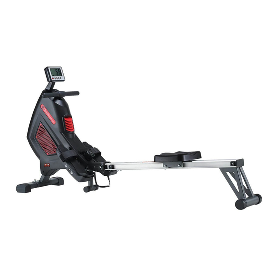
- Page 1 BR-2712 FOLDABLE FAN/AIR ROWER www.body--sculpture.com...
-
Page 2: Table Of Contents
…………….………………………… Important Safet y Information ……………………………… Exploded- View Assembl y Draw ing ……………………………………………………………………………… 3 Parts List ………………………………………………………... 5 Assembl y Instructions Folding For St orage ………………………………………………………………….. 10 ……………………………………………………………………… 11 Exerci se Guide ……………………………………………………… Exerci se Instructions ……………………………………………………… Exerci se Computer... -
Page 4: Important Safet Y Information
Please keep this manual in a safe place for easy reference. 1. It is important to read this entire manual before assembling and using the equipment. Safe and effective use can only be achieved if the equipment is assembled, maintained and used properly. -
Page 6: Parts List
PART LIST DESCRIPTION DESCRIPTION Spring set End cap Fan set Stopper Magnet set Lower connect tube cover Roller set Upper connect tube cover Front stabilizer end cap (L) Pedal Front stabilizer end cap (R) Adjustment pedal plate Seat rail Left chain cover Fan cover Right chain cover Rectangle end cap... - Page 7 PART LIST DESCRIPTION DESCRIPTION Screw (M5*12) Screw (ST4.2*15) Screw (M6*20) Flat washer (Φ6.5) Screw (M8*15) Flat washer (Φ8.5) Screw (M8*20) Flat washer (Φ8.4) Screw (M8*35) Flat washer (Φ10.3) Screw (M5*20) Flat washer (Φ6.1) Screw (M6*45) Upper sensor wire Screw (ST2.9*15) Lower sensor wire Screw (ST4.2*20) Wrench...
-
Page 8: Assembl Y Instructions
STEP 1 1. Attach the Front stabilizer (44) to the Main frame (12) using 2 sets of Bolt (M8x55) (51), Flat washer (Ø8.4) (70) and Domed nut (M8) (56). 2. Pull out the Ball pin (14) as per illustration A. 3. - Page 9 STEP 2 1. Pass the Seat rail (7) through the Seat support (10). 2. Insert the Rectangle end cap (9) into the Seat rail (7). 3. Attach the Rear stabilizer (13) to the Seat rail (7) using 4 sets of Flat washers (Φ8.4) (70) and Screws (M8x20) (60).
- Page 10 STEP 3 1. Connect the Upper sensor wire (73) with the Lower sensor wire (74). 2. Attach the Seat rail (7) to the Connect tube (11) using 6 sets of Flat washers (Φ8.4) (70) and Screws (M8x20) (60). 3. Attach the Stopper (30) to the Seat rail (7) using 2 Screws (M6x20) (58).
- Page 11 You can adjust the tension control knob by turning in the direction of “+” for more resistance, or by “-“ for less resistance. It depends on your fitness and personal health. STEP 4 Attach the Adjustment pedal plate (34) to the Pedal (33) as per illustration A & B. 2.
- Page 12 The pedal strap is adjustable and can be personalized to fit the user’s foot size. To adjust the pedal strap, remove the Velcro end of the strap from the mesh side by pulling it upward and then to the left. Once removed, you may increase the opening of the pedal strap by pulling the mesh end up and to the right.
-
Page 13: Folding For St Orage
1. Pull out the Ball pin (14). 2. Turn the rail to 90 degrees. 3. Insert the Ball pin (14) into to the B hole. You can adjustment the pedal plate (34) to your foot size. -
Page 14: Exerci Se Guide
Rowing is an extremely effective form of exercise. It strengthens the heart and improves circulation as well as exercising all the major muscle groups; the back, waist, arms, shoulders, hips and legs. The Basic Rowing Stroke Sit on the saddle and fasten your feet to the pedals using the Velcro straps. Then take hold of the rowing bar. Take up the starting position, leaning forward with your arms straight and knees bent as shown in (Fig 1). -
Page 15: Exerci Se Instructions
Using your FAN ROWER will provide you with several benefits, it will improve your physical fitness, tone muscle and in conjunction with a calorie-controlled diet help you lose weight. 1. The Warm Up Phase This stage helps get the blood flowing around the body and the muscles working properly. It will also reduce the risk of cramp and muscle injury. -
Page 16: Exerci Se Computer
DISPLAY FUNCTION: ITEM DESCRIPTION . The sequence of display: TMR→CNT→CAL→TOTAL CNT SCAN . In SCAN mode, press MODE key to choose other functions. . Automatically scan through each mode in sequence every 6 seconds. . W/O setting the target value, time will count up. . - Page 17 BUTTON FUNCTION: ITEM DESCRIPTION . Press UP Key to increase value. Press and hold the Key to increase value faster. . TMR setting range: 0:00~99:00 (Each increment is 1:00) . CAL setting range: 0.0~999.0 (Each increment is 1.0) . Press DOWN Key to decrease value. Press and hold the Key to decrease the value faster.
- Page 18 Trouble shooting: . When the display of LCD is dim, it means the batteries need to be changed. . If there is no signal when you pedal, please check if the cable is well connected. NOTE: 1. Stop training for 4 minutes, the main screen will be off. 2.
- Page 19 Use this space to record your own exercise routine results...
- Page 20 COPYRIGHT ©2018 BY BODY SCULPTURE INTERNATIONAL EUROPE LTD ALL RIGHTS RESERVED. UNAUTHORIZED DUPLICATION IS A VIOLATION OF LAW.
Need help?
Do you have a question about the BR-2712 and is the answer not in the manual?
Questions and answers