Table of Contents
Advertisement
Advertisement
Table of Contents

Related Manuals for EGOpro Safe MOVE 4.0

Summary of Contents for EGOpro Safe MOVE 4.0
- Page 1 EGOpro Safe MOVE 4.0 Use and Installation Manual (V01)
-
Page 2: Table Of Contents
TABLE OF REVISIONS TABLE OF CONTENTS 1 TABLE OF REVISIONS 2 CONFORMITY 3 SAFETY INSTRUCTIONS 3.1 DISPOSAL 3.2 LIMITATIONS FOR USE 4 INTRODUCTION 4.1 INTENDED USE 4.2 SYMBOLS 5 BASIC KIT COMPONENTS 6 SYSTEM OPERATION 6.1 PEDESTRIAN WORKER PRE-WARNING 6.2 PEDESTRIAN WORKER WARNING 6.3 VEHICLE-VEHICLE WARNING 7 PLACING TAGS 7.1 HELMET TAG FITTING... - Page 3 TABLE OF REVISIONS 8.5 EXPANSION OF THE NUMBER OF SENSORS 8.6 STOPPING DISTANCES AND ACTIVATION DISTANCES 8.7 V EHICLE DECELERATION AND DRIVER S RESPONSE DISTANCES 8.8 S YSTEM ACTIVATION DISTANCES ETTING THE POWERS TRANSMITTED 8.9 C ALCULATING THE DISTANCE IN CASE OF VEHICLE VEHICLE COLLISION 9 TURNING-ON AND CONFIGURATION 9.1 TURNING ON THE SYSTEM...
- Page 4 TABLE OF REVISIONS 11.8 USERS 11.8.1 ADDING/EDITING USERS 11.8.2 IMPORTING/EXPORTING USERS 12 OPTIONAL MODULES 12.1 DISPLAY OVERVIEW WITH ACTIVE MODULES 12.2 NON-ACTIVE MODULE ALARM 13 VEHICLE-VEHICLE ANTI-COLLISION MODULE 13.1 INSTALLATION 13.2 ALARM VISUALISATION 13.3 SENSORS POWER 14 FILTER MODULE 14.1 INSTALLATION 14.2 CONNECTIONS AND HW CONFIGURATIONS 14.3 VISUALISATION 14.4 CONFIGURATION...
- Page 5 TABLE OF REVISIONS 18.1 INSTALLATION 18.2 VISUALISATION 18.3 AISLE POWER SETTING 18.4 AISLE POWER SETTING | VEHICLE- VEHICLE 19 WI-FI MODULE 19.1 INSTALLATION 19.1.1 WI-FI ANTENNA 19.1.2 CELLULAR ROUTER 19.2 VISUALISATION 19.3 DATA TRANSFER 19.4 REMOTE CONTROL 20 CHECKLIST MODULE 20.1 VISUALISATION 20.2 TEST RESULT 20.3 CONFIGURATION...
-
Page 6: Table Of Revisions
TABLE OF REVISIONS 24.2 SAFE MOVE CPU CONNECTION 24.3 HUB-SENSORS CONNECTION 24.4 SENSORS CONNECTION 24.5 SAFE MOVE POWER DISTRIBUTION 24.6 SAFE MOVE POWER DISTRIBUTION (HIGH VOLTAGE BATTERY) 24.7 W MODULE CONNECTION 24.8 CELLULAR MODEM CONNECTION 24.9 BADGE READER CONNECTION 24.10 HUB EXTENSION (UP TO 8 SENSORS) 24.11 AISLE SENSORS CONNECTION 24.12 SPEED SENSOR CONNECTION 24.13 SHOCK SENSOR CONNECTION... -
Page 7: Conformity
The EGOpro Safe MOVE 4.0 system does not replace the driver’s attention and judgement or need to slow down or brake in case of danger, and it does not exonerate the purchaser and the driver from adopting the usual safety procedures expected. -
Page 8: Introduction
4.1 INTENDED USE The EGOpro Safe MOVE 4.0 System is a safety supporting system that is used for detecting the presence of pedestrian workers and vehicles equipped with suitable devices. When either are detected, sound and visual signals are generated, to which the I/O that are present in the system can be associated. -
Page 9: Basic Kit Components
BASIC KIT COMPONENTS 5 BASIC KIT COMPONENTS The EGOpro Safe MOVE 4.0 basic kit consists of: P LX SAFEMOVE DIS - Display with cable (plate and joint included) P LX SAFEMOVE SENS4 - SAFE MOVE 4.0 multifunction sensor. -
Page 10: System Operation
6 SYSTEM OPERATION The solution offered by the EGOpro Safe MOVE 4.0 proximity warning & alert system minimises the potential for accidents between forklifts and operators on foot in common working areas. Through visual and sound alarms, the system warns the driver, in real time, of the presence and position of pedestrian workers wearing active PPE who enter the danger zones around the vehicle in motion. -
Page 11: Placing Tags
PLACING TAGS 7 PLACING TAGS 7.1 HELMET TAG FITTING To fit the PLX TAGSAFETY 03TH Tag, you first need to clean the helmet. Then, you have to suitably remove the grease from the surface with the napkin supplied. Now you can affix the Tag as shown in the figure. 7.2 WEARABLE TAG ACCESSORIES The wearable Tag is supplied together with a series of accessories that guarantee a wide range of options for wearing it. -
Page 12: Procedure For Changing The Battery
PLACING TAGS 7.3 PROCEDURE FOR CHANGING THE BATTERY The battery inside the Tag is a CR2450 button cell battery. To replace it, remove the yellow rubber piece, and then replace the battery. Caution: respect the correct polarity; insert the battery with the negative pole towards the circuit. -
Page 13: Installation On The Vehicle
INSTALLATION ON THE VEHICLE 8 INSTALLATION ON THE VEHICLE 8.1 SYSTEM ARCHITECTURE AND GENERAL INSTRUCTIONS The basic KIT of the EGOpro Safe MOVE 4.0 system that is installed on the vehicle consists of the following devices: 3 Sensors 1 HUB ... - Page 14 INSTALLATION ON THE VEHICLE The technical materials and information contained in this document are strictly confidential and the exclusive property of Advanced Microwave Engineering s.r.l. These materials and information are intended solely for the purpose designated and may not be used otherwise. It is not permitted to disclose or reproduce them in whole or in part without express written permission.
-
Page 15: Positioning The Devices
INSTALLATION ON THE VEHICLE 8.2 POSITIONING THE DEVICES To position the devices, take into account the operation characteristics of the system, the mechanical restrictions and the IP protection degree of the devices. For these reasons, two categories are identified: Devices outside the driver’s cabin ... -
Page 16: Positioning The Control Unit (Cpu)
INSTALLATION ON THE VEHICLE 8.2.1 Positioning the control unit (CPU) The CPU is the basic element of the system and it can be positioned at any point inside the driver's cabin. The position of the CPU must not obstruct the driver’s and the vehicle operability, and it should be handy to connect the HUB and the Display. -
Page 17: Positioning The Display
INSTALLATION ON THE VEHICLE 8.2.2 Positioning the Display The Display must be positioned inside the driver’s cabin in accordance with the driver’s visibility requirements and taking into account the CPU position: the connection cable between Display and CPU is 2.5 m long. When installing the Display and laying the connection cable, be careful so that they do not disturb the driver’... -
Page 18: Positioning The Hub
INSTALLATION ON THE VEHICLE NOTE: the mechanical joint supplied can be used to obtain the desired inclination. Front sensors must have a slight orientation towards the outside. For example, for a counterbalanced vehicle, they must be positioned outside the moulding of the fork/gripper holder mounting, and they must have an orientation angle towards the outside of around 20°. -
Page 19: Connections
INSTALLATION ON THE VEHICLE 8.3 CONNECTIONS 8.3.1 General instructions The necessary connections on the systems can be summarised in two categories: Data Connections Power Supply Connections Data Connections The data connection between the system devices is established with a UTP cable. As a minimum requirement, it is recommended to use a UTP cable belonging to category 5E or higher. - Page 20 INSTALLATION ON THE VEHICLE Power Supply Connection The system must be powered in direct current (VDC) ranging from 12V to 24V (±10%). The devices to be powered are the CPU and the HUB. A direct positive wire (VIN) and a positive wire under key (VQ) must arrive to the CPU, whereas only the direct positive wire protected by an ATO fuse (4A/32V) must arrive to the Hub.
-
Page 21: Cpu Wiring
INSTALLATION ON THE VEHICLE 8.3.2 CPU Wiring All the devices of the system must be connected to the CPU. The available connectors are as follows: PWR-IN USB1 RELAY2 RELAY1 USB2 RS232 SENSORS DISPLAY Power supply Display Relay /turning-on Sensors connector (RJ45) RS 232 Power supply/turning-on... -
Page 22: Connecting Sensors
INSTALLATION ON THE VEHICLE To connect the HUB, an UTP cable belonging to Cat. 5e or higher must be connected to one of the Sensors ports. The CPU has 2 relays that can be controlled independently. There are 3 pins for each relay: - NO | normally open - C | common - NC | normally closed. - Page 23 INSTALLATION ON THE VEHICLE A1 – MW transmission antenna uFL connector (antenna already connected) LED1 – vehicle-vehicle reception signal (flashing) A2 – MW reception antenna uFL connector (antenna to be connected) LED2 – LF transmission (flashing) and diagnosis error (steady off) A3 –...
-
Page 24: Connecting The Hub
INSTALLATION ON THE VEHICLE 8.3.4 Connecting the HUB Connect the sensors to BUS 2 by means of UTP cable following the indications given in the sensor connection section. When crimping the UTP cable, follow the same sequence of colours on each cable end. Connect the HUB to the CPU by means of the BUS 1 connector using a cable belonging to CAT. - Page 25 INSTALLATION ON THE VEHICLE If the device is installed on electric vehicles, add a power line filter, for instance an FN2090-3-06 Schaffner filter. If requested, the relays present on the board can be connected following the diagram foreseen. The default configuration indicates that: ...
-
Page 26: Installing The System With M12 Connectors
INSTALLATION ON THE VEHICLE 8.4 INSTALLING THE SYSTEM WITH M12 CONNECTORS The PLX SAFEMOVE SENS 4 and PLX SAFEMOVE HUB 4 devices are available in a version fitted with M12 connectors. Such version has been designed in order to make the system installation and removal simpler and quicker. The table below summarises the codes used in the system fitted with connectors. -
Page 27: Length Of Connections
INSTALLATION ON THE VEHICLE Colour Function FEMALE (FRONT VIEW) Brown Blue White Green Pink Normally Open Relay 1 Yellow Common Relay 1 Black Normally Closed Relay 1 Grey Normally Open Relay 2 Common Relay 2 Violet Normally Closed Relay 2 Grey-Pink Not Used Red-Blue... -
Page 28: Expansion Of The Number Of Sensors
LED TX LED RX LED PWRON Find below an example of the configuration of an EGOpro Safe Move system with 8 sensors. SPLITTER 1 SPLITTER 2 The technical materials and information contained in this document are strictly confidential and the exclusive property of Advanced Microwave Engineering s.r.l. -
Page 29: Stopping Distances And Activation Distances
INSTALLATION ON THE VEHICLE STOPPING DISTANCES AND ACTIVATION DISTANCES When installing a safety supporting system to be used for reducing the risk of man-vehicle and vehicle-vehicle collisions, it is necessary to take into account which activation distances have to be considered for the system operation. The purpose of this is to adjust the system so that a truly helpful signal can be given to the pedestrian worker. - Page 30 INSTALLATION ON THE VEHICLE 10.9 11.8 12.8 13.8 14.8 10.1 15.9 10.9 17.0 11.8 18.2 12.7 19.3 Chart 2 Calculation of stopping distance as per ISO 6292 A2 (<16000 kg) Total Speed Deceleration distance Driver reaction braking [km/h] [m] ISO6292 A2 distance @1s [m] time [m] 10.8...
-
Page 31: Setting The Powers Transmitted
INSTALLATION ON THE VEHICLE 8.8 System activation distances. Setting the powers transmitted The section above dealt with how to calculate stopping distances for an industrial vehicle. When estimating the distances at which a tag potentially in danger of collision should be detected, a distance margin should be considered as well. A zero distance cannot and should not be set. -
Page 32: Calculating The Distance In Case Of Vehicle-Vehicle Collision
INSTALLATION ON THE VEHICLE 8.9 Calculating the distance in case of vehicle-vehicle collision. In case of vehicle-vehicle collision, we can consider that the same assessments described in the sections above are applicable. The worst case to be considered is the one in which vehicles move at maximum speed against each other. In this case, the calculated distance is twice the one that was calculated before. -
Page 33: Turning-On And Configuration
TURNING-ON AND CONFIGURATION 9 TURNING-ON AND CONFIGURATION 9.1 TURNING ON THE SYSTEM The system turns on automatically when the power supply (12/24V ) is connected. While the system is turned on for the first time, the initialisation screen is displayed. Once initialisation is completed, the following screen is showed. -
Page 34: Configuration
TURNING-ON AND CONFIGURATION 9.2 CONFIGURATION In order for sensors to be recognised by the system, they must be configured from the configuration menu via the touchscreen. The following procedure describes the steps to be followed in order to configure the system and make sure that the peripheral devices are correctly connected. -
Page 35: Step 3 | Sensors
TURNING-ON AND CONFIGURATION 9.2.3 STEP 3 | SENSORS The first screen when accessing the configuration menu is the following one. To configure the sensors press the SENSORS key. To configure the sensors press the SENSORS SEARCH key. The technical materials and information contained in this document are strictly confidential and the exclusive property of Advanced Microwave Engineering s.r.l. These materials and information are intended solely for the purpose designated and may not be used otherwise. -
Page 36: Step 4 | Sensors Search
TURNING-ON AND CONFIGURATION 9.2.4 STEP 4 | SENSORS SEARCH Each sensor has an unequivocal ID that must be saved to the CPU: first perform the ID SEARCH and then the SENSORS SEARCH. Before starting the ID SEARCH, make sure that the selectors present on the HUB and on each sensor are set to The sensors and the HUB, if they have an M12 connector, are already correctly set, and they must not be opened. -
Page 37: Step 5 | Searching Sensors By Id
TURNING-ON AND CONFIGURATION 9.2.5 STEP 5 | SEARCHING SENSORS BY ID The search sensors by ID function is used to associate each sensor ID (Factory Code uniquely assigned by the manufacturer) with a number from 1 to 8 that identifies its position compared to the vehicle, in order to facilitate the subsequent system calibration operations. - Page 38 TURNING-ON AND CONFIGURATION If some sensors have not been identified, try repeating the search operation. If it still fails, check: Position of all selectors (they must be set to 0) Connections between sensor and HUB. If no sensor is identified, check: ...
- Page 39 TURNING-ON AND CONFIGURATION If the allocation procedure has been successful, the sensors turn green and the associated IDs move to the new positions. In case of error, try making the allocation again. Press BACK and return to the previous screen. The technical materials and information contained in this document are strictly confidential and the exclusive property of Advanced Microwave Engineering s.r.l.
-
Page 40: Step 6 | Searching Sensors By Position
TURNING-ON AND CONFIGURATION 9.2.6 STEP 6 | SEARCHING SENSORS BY POSITION This step checks the correct operation of the sensors and saves them to the system. Press SENSORS SEARCH (STEP 4 screen). The search for sensors starts automatically. If the ID search has been correctly performed, the selected sensors (e.g. 2, 5 and 8) will turn yellow. Press the SAVE SETTINGS key: the colour of the sensors will change from yellow to green, and, as of that moment, the sensors will be associated to the vehicle. -
Page 41: Searching Sensors Without Id
TURNING-ON AND CONFIGURATION 9.2.7 SEARCHING SENSORS WITHOUT ID A fixed position can be assigned to the sensors without making the ID search. In this case, place the selector present on each sensor in the desired position. For example, for the basic kit: ... -
Page 42: Tag Detection Test
TURNING-ON AND CONFIGURATION 9.3.2 TAG DETECTION TEST Move a Tag close to each of the sensors installed and check their operation. The transponder detection in Pre-Warning is yellow. The yellow sectors correspond to the sensor that has detected the Tag and indicate the Tag position with respect to the vehicle. The transponder detection in Warning is red. -
Page 43: Operation Modes
10 OPERATION MODES 10.1 DISPLAY OVERVIEW Main screen of EGOpro Safe MOVE 4.0 with 3 sensors installed without any detection of pedestrian workers or vehicles. In addition, the following elements are also displayed on the screen: 1. Date and time 2. -
Page 44: Pedestrian Worker's Tag Display Alarm: Pre-Warning
OPERATION MODES 10.2 PEDESTRIAN WORKER’S TAG DISPLAY ALARM: PRE-WARNING The presence of the pedestrian worker wearing an active TAG within the PRE-WARNING activation range is signalled to the driver via the display that shows the position of the pedestrian worker around the vehicle. Lighted up sectors are associated to the sensor and they are coloured according to the sensor detecting the Tag, and so the pedestrian worker’s position. -
Page 45: Pedestrian Worker's Tag Display Alarm: Warning
OPERATION MODES 10.3 PEDESTRIAN WORKER’S TAG DISPLAY ALARM: WARNING The presence of the pedestrian worker wearing an active TAG within the WARNING activation range is signalled to the driver via the display by means of a clearly visible red ring. The PRE-WARNING alarm indication remains visible and helps the driver locate the personnel on foot. -
Page 46: Sensors And Hub Diagnosis
OPERATION MODES 10.4 SENSORS AND HUB DIAGNOSIS Active sensors are displayed matching their position on the vehicle. Only fitted and configured sensors are shown on the display. The system is equipped with a self-diagnosis function that constantly checks the correct operation of the devices. If the icon of the sensor is GREEN, it means that the diagnosis system did not detect any anomalies on that specific sensor. -
Page 47: Driver Login
OPERATION MODES 10.5 DRIVER LOGIN The LOGIN operation is used to check which operator is driving the vehicle at the date and time requested, and it is essential to exclude the driver’s TAG from the anti-collision system. When the system is turned on, the main interface presents a lateral red message inviting the user to LOGIN, which is signalled by a yellow icon. - Page 48 OPERATION MODES For the login operation, enter the unequivocal ID in the space: USERCODE: unequivocal numerical code of 6 figures: the code usually coincides with the TAG own code. Use the numerical keyboard to enter the code. To delete only one character: To delete all characters together: Once the code has been entered, press OK.
-
Page 49: Data Access
OPERATION MODES 10.6 DATA ACCESS Press the key with the USB icon and enter the relevant password to access the data page in which the history of events is shown. Up to 1,000 events can be displayed, including: • TAGS detected with the following information: detected TAG code - activated sensor - date and time - position (if the GPS module is enabled) •... -
Page 50: Basic Configuration
BASIC CONFIGURATION 11 BASIC CONFIGURATION 11.1 ACCESS TO MENU Press the CONFIGURATION icon to access the menu To access the system configuration section, a password must be entered so that only the enabled user can view this screen. The default password is 1234. The technical materials and information contained in this document are strictly confidential and the exclusive property of Advanced Microwave Engineering s.r.l. -
Page 51: Reboot
BASIC CONFIGURATION 11.2 REBOOT To reboot or stop the system, enter the specific password and open the configuration menu. CLOSE key to reboot the system. If necessary, press this key to reboot the system. This key is shown in all the configuration screens If the system is turned off, you will need to disconnect and reconnect power to restart it. -
Page 52: Configuration Menu
BASIC CONFIGURATION 11.3 CONFIGURATION MENU In the configuration menu, you can: Set the system Time and Date Configure the Modes of the alarms Configure the sensors (System Calibration) Select the language preferred Set the master data of users/drivers ... -
Page 53: Clock & Date
BASIC CONFIGURATION 11.4 CLOCK & DATE Press the CLOCK & DATE icon to access the settings 11.4.1 MANUAL In manual mode, the internal clock of the system must be set by filling in all the fields manually. On the display, touch the field to be changed and use the numerical keyboard located on the right to delete the old value and set the new one. -
Page 54: Automatic
BASIC CONFIGURATION 11.4.2 AUTOMATIC In automatic mode, the internal clock of the system becomes automatically synchronised by means of the network (if available) or the GPS module, if installed. Use the side arrows to scroll the list and select the correct time zone, the system will update the time automatically. 1. -
Page 55: Alarm Configuration
BASIC CONFIGURATION 11.5 ALARM CONFIGURATION Press the ALARM CONFIGURATION icon to access the settings The alarm modes are set by means of this interface. 1. VOLUME LEVEL Press keys to increase or decrease the volume of the loudspeaker. Press ‘Audio Test’ to start a test (the 'Tag In' sound and the 'Tag Stay' sound will be reproduced consecutively). ... - Page 56 BASIC CONFIGURATION 2. ALARM MODES It defines the mode in which the driver is warned about the presence of personnel wearing an active PPE (TAG) within a dangerous area. The value, between 1 and 5, defines 5 modes referring to the time elapsed between one alarm sound and the next when a dangerous condition remains.
-
Page 57: Sensors Configuration
BASIC CONFIGURATION 11.6 SENSORS CONFIGURATION Press the SENSORS CONFIGURATION icon to access the settings The sensors configuration menu includes 4 STEPS: 1. Sensors Search Tool to detect and save the sensors fitted. 2. Sensors Power Tool to set the system operating range. 3. -
Page 58: Sensors Power
BASIC CONFIGURATION 11.6.2 SENSORS POWER Press the SENSORS POWER icon to access the settings Select LR SENSORS POWER to configure the Pre-warning alarm range Select SR SENSORS POWER to configure the Warning alarm range Before adjusting the system power, carefully read chapter 8.6: STOPPING DISTANCES. The technical materials and information contained in this document are strictly confidential and the exclusive property of Advanced Microwave Engineering s.r.l. -
Page 59: Lr Sensors Power
BASIC CONFIGURATION 11.6.3 LR SENSORS POWER Adjust the LR sensor power to change detection distance of the Tag as well as that of the pedestrian worker in the Pre- Warning area. In order to change the power of sensors: Select the sensor by pressing the corresponding icon: the selection will be highlighted by a green ring around the icon. -
Page 60: Sr Sensors Power
BASIC CONFIGURATION 11.6.4 SR SENSORS POWER Adjust the SR sensor power to change the detection distance of the Tag as well as that of the pedestrian worker in the Pre-Warning area. In order to change the power of sensors: Select the sensor by pressing the corresponding icon: the selection will be highlighted by a green ring around the icon. -
Page 61: Tag Settings
BASIC CONFIGURATION 11.6.5 TAG SETTINGS When a pedestrian worker wearing an active PPE enters into a dangerous area around a vehicle, the TAG will be activated and a warning sound with an adjustable intermittent tone will be triggered. Tag Settings: time, expressed in seconds, that elapses between one sound alarm and the next in the user’s Tag, when he is within the detection range of a sensor. -
Page 62: Language
BASIC CONFIGURATION 11.7 LANGUAGE Press the dedicated key to select the language chosen. These are the settable languages: 1. Italian 2. English 3. French 4. Spanish The technical materials and information contained in this document are strictly confidential and the exclusive property of Advanced Microwave Engineering s.r.l. These materials and information are intended solely for the purpose designated and may not be used otherwise. -
Page 63: Users
BASIC CONFIGURATION 11.8 USERS The Users section shows the codes of the Tags that were entered into the system master data for login and logout (section 10.5). To change the master data and see the users’ codes, log in as an administrator. The default code for administrators is 9999. -
Page 64: Adding/Editing Users
BASIC CONFIGURATION 11.8.1 ADDING/EDITING USERS Fill in the following boxes for master data to add or edit a user: ‘User code’ Enter the code to be associated to the Tag to be used to log in. The user code will be the code saved and displayed in the file of events. -
Page 65: Importing/Exporting Users
‘Upload Config.’ This is used to import the list of users from a USB key. Before importing all the data of users, they will be deleted from the database of the EGOpro Safe Move system. The list of users is saved in the ‘MoveDB.csv’ file. ‘csv’ files are delimited text files that use a semicolon to separate values. - Page 66 BASIC CONFIGURATION DATE MODIFY: date in the dd/MM/yyyy format [NOT MANDATORY] LAST LOGIN: date in the dd/MM/yyyy format [NOT MANDATORY] CODE TAG: max. 6 digit, numerical [NOT MANDATORY] CODE BADGE: alphanumeric [NOT MANDATORY] NOTES: The username field must be unequivocal, and it is used to log in. ...
-
Page 67: Optional Modules
An authorised technician is required to activate any additional licenses. 12.1 DISPLAY OVERVIEW WITH ACTIVE MODULES Main screen of an EGOpro Safe MOVE 4.0 with optional modules activated. 1. Status of the Warning detection 2. Icons indicating the status of modules acquired by the customer:... -
Page 68: Non-Active Module Alarm
OPTIONAL MODULES 12.2 NON-ACTIVE MODULE ALARM On the left side of the display, only the status icons for the different modules acquired by the user are shown. The icon of the modules can be red or green, depending on the status of the module. The icon status for each module will be explained further on in the manual. -
Page 69: Vehicle-Vehicle Anti-Collision Module
In this case, there are three visual alarms: WHITE: it warns about the presence of other vehicles equipped with the EGOpro Safe MOVE system in a dangerous area around the vehicle. The direction from which the other vehicle is coming is indicated by the sectors. -
Page 70: Sensors Power
VEHICLE-VEHICLE ANTI-COLLISION MODULE 13.3 SENSORS POWER In this section, the sensor power, and thus the detection distance of both the pedestrian worker’s Tag and the vehicle’s Tag, can be changed. To configure the sensor power with respect to the vehicle’s Tag, press the ‘VEHICLE’ key, and carry out all the same operations performed for the pedestrian worker’s Tag (section 11.6.3). -
Page 71: Filter Module
FILTER MODULE 14 FILTER MODULE The filter sens (P LX FILTER SENS), or inhibitor, is a device used to delimit a zone within which, in accordance with the client's safety needs, the tags are temporarily disabled. This device is found in the cabin of the vehicle; in this way, the driver can wear a Tag while driving without being detected by the system. -
Page 72: Connections And Hw Configurations
FILTER MODULE 14.2 CONNECTIONS AND HW CONFIGURATIONS The connection requires only one UTP cable, Cat. 5E or higher (LAN) between the device and one of the free 'Sensor' ports in the CPU of the system. FILTER SENS ADDRESS SELECTOR LED1-6 ADR_TX BUS2 UTP CONNECTION... -
Page 73: Visualisation
FILTER MODULE 14.3 VISUALISATION The icon of the Filter module is green: the module is working. The number next to the icon indicates the number of Tags that have been temporarily disabled. To reactivate them, exit the sensor activation zone and wait for 3 seconds. -
Page 74: Configuration
FILTER MODULE 14.4 CONFIGURATION To modify the range the module covers of the module, access the configuration menu 'SENSORSTAG SETTINGS' (see section 11.6). To configure the Filters Sens module, do as follows: Press the 'Filter Sensor Search' key to associate the sensor to the System. If the module is correctly recognised, the icon will become yellow. -
Page 75: Auto Login
FILTER MODULE 14.5 AUTO LOGIN The AUTO LOGIN allows any worker wearing a Tag to login automatically. To enable the AUTO LOGIN function, the Filter Sens module must be installed and operational. Press the yellow login icon to run the AUTO-LOGIN function. If the system detects only one TAG, the code is displayed and then, after 3 seconds, the screen goes back to the main monitor. -
Page 76: Badge Module
BADGE MODULE 15 BADGE MODULE You can also log in to the system by means of the badge reader external to the system. The driver is automatically identified and LOGS IN immediately after passing the badge over the reader connected to the system. -
Page 77: Badge Association
BADGE MODULE The LOGOUT operation is essential to be able to make the driver’s Tag visible again for the anti-collision system. When the system is turned off, the LOGOUT operation is automatically performed. 15.3 BADGE ASSOCIATION In order to log in with the badge, the Tag must be associated to the badge. Go to the user section in the configuration menu in order to view the master data of the Tags. - Page 78 BADGE MODULE In the Edit or Add section, follow these operations to associate a Tag to the badge and to log in with the badge reader: 1. Pass the badge over the reader and the ID will appear at the bottom on the left side of the display under the word BADGE.
-
Page 79: Tracking Adaptive Range Module
TRACKING ADAPTIVE RANGE MODULE 16 TRACKING ADAPTIVE RANGE MODULE The 'Tracking Adaptive Range' function, or the adaptive function, automatically adapts the detection distance (range) according to the speed of the vehicle. It is a software module to be combined with a hardware module to acquire the speed of the vehicle. The hardware modules that acquire the speed of the vehicle are: ... -
Page 80: Adaptive Sensor Power
TRACKING ADAPTIVE RANGE MODULE 16.2 ADAPTIVE SENSOR POWER The power of the sensor is adjusted depending on the speed, and is determined as the sum of two components: Fixed part - 'Sensors normalization': it is the minimum power value, used when the vehicle is at standstill (speed = 0 km/h). - Page 81 TRACKING ADAPTIVE RANGE MODULE The increase values, for both ground conditions, are shown in the table below. Power level increase Power level increase (step %) (step %) Speed Range (km/h) DRY mode WET mode The technical materials and information contained in this document are strictly confidential and the exclusive property of Advanced Microwave Engineering s.r.l. These materials and information are intended solely for the purpose designated and may not be used otherwise.
- Page 82 TRACKING ADAPTIVE RANGE MODULE Incremento Potenza in funzione della velocità Asciutto Bagnato Velocità (km/h) For example: Normalization Speed Dry power Wet power 4 km/h 12+16=28% 12+20=32% See chapter 8.6 for the ratio between sensor power and detection distance. The technical materials and information contained in this document are strictly confidential and the exclusive property of Advanced Microwave Engineering s.r.l. These materials and information are intended solely for the purpose designated and may not be used otherwise.
-
Page 83: Sensors Normalization
TRACKING ADAPTIVE RANGE MODULE 16.2.1 SENSORS NORMALIZATION The 'Sensors normalization' function defines the detection distance when the vehicle is at standstill (speed=0 km/h). In order to set the power level (range) or the detection distance, carry out the following operations: ... -
Page 84: Emergency Level
TRACKING ADAPTIVE RANGE MODULE 16.2.2 EMERGENCY LEVEL The 'Emergency level' function defines the maximum speed and the detection distance automatically if the system CANNOT establish the speed of the vehicle. (e.g., when the satellite coverage is not enough or there is a GPS module failure). -
Page 85: Gps Module
GPS MODULE 17 GPS MODULE In order to have this module available, the CPU must be in GPS mode. By means of this device, the system can detect the speed and the position of the vehicle. The speed is necessary to enable the ADAPTIVITY function. -
Page 86: Gps Visualisation
GPS MODULE 17.2 GPS VISUALISATION The icon of GPS module is green: the system is receiving data from the GPS antenna. If the icon of the GPS module is red: the system is not receiving the signal from the GPS antenna or the GPS signal is interrupted. -
Page 87: Aisle Module
AISLE MODULE 18 AISLE MODULE Find below the codes associated to this module. Code Quantity Description GECMPPF204530 UB1000 Ultrasonic sensor GECMPPF116454 5-pole M12 cable for ultrasonic sensor; 10 m SWAISLE Software module The AISLE module includes the proximity sensor that must be fitted correctly at the sides of the vehicle. With this device, the system can capture information if the vehicle is, for example, inside the aisle of the warehouse, and therefore, visibility is poor. -
Page 88: Visualisation
AISLE MODULE 18.2 VISUALISATION When the vehicle is in AISLE mode, the system automatically increases or decreases the range of activation of the sensors (depending on how the module was configured when the license was activated). The icon of the AISLE module is green: the system is receiving data from the sensor, and the vehicle is in the aisle, so the AISLE function is activated. -
Page 89: Aisle Power Setting
AISLE MODULE 18.3 AISLE POWER SETTING In this section, the sensor power can be changed as well as the detection distance of the worker’s Tag and the AISLE mode. Firstly, press the 'MAN' key and carry out the operations in section 11.6.3 to set the sensor power compared to the operator's Tag. -
Page 90: Aisle Power Setting | Vehicle- Vehicle
AISLE MODULE 18.4 AISLE POWER SETTING | VEHICLE- VEHICLE In this section, the sensor power can be changed as well as the detection distance of the worker's Tag if the vehicle is in the aisle and the AISLE module is activated. The detection distance of the rest of the vehicles can be set too. Firstly, press the 'MAN' key and carry out the operations in section 11.6.3 to set the sensor power compared to the operator's Tag. -
Page 91: Wi-Fi Module
WI-FI MODULE 19 WI-FI MODULE With the WI-FI module, after a hardware module is installed, data can be automatically downloaded, directly to the server, and the system can be remotely controlled. 19.1 INSTALLATION 19.1.1 WI-FI ANTENNA Ubiquiti BULLET M2-HP The Wi-Fi module must be connected directly to the LAN port of the CPU. The default LAN features a POE, so no external power is required. -
Page 92: Cellular Router
WI-FI MODULE 19.1.2 CELLULAR ROUTER Robustel R3000-L4L This module is a cellular router for internet connection via 3G or 4G network (depending on the SIM used). The router is connected to the LAN port of the CPU with the dedicated cable supplied with the device that cuts off power to the POE. - Page 93 WI-FI MODULE The figure below shows the control panel where the status of the router is displayed. CHANGING USER NAME AND PASSWORD For security reasons, change both user name and password after the first login. To change username and password, access the 'System> User Management' section from the control panel. The technical materials and information contained in this document are strictly confidential and the exclusive property of Advanced Microwave Engineering s.r.l.
- Page 94 WI-FI MODULE SIM PARAMETERS Enter the SIM parameters in the 'Interface> Cellular' section so that the router connects to the internet. In the "Interface> Link Manager" section, enter the APN and Dialup parameters provided by the operator. REMOTE CONNECTION If the remote connection is to be enabled, first enable the DDNS service and configure the forwarding of ports 22 (ssh) and 5900 (vnc).
- Page 95 WI-FI MODULE When forwarding ports, enter the IP address that will be assigned to the CPU in the 'Local IP' field. For the ssh port, it is safer to open an alternative port (e.g., 222) and forward to port 22. After all the configurations are set, press 'Save &...
-
Page 96: Visualisation
WI-FI MODULE When the network is disconnected, these three LEDs indicate the possible cause of the problem. Errors are encoded using a binary code; the order of the LEDs follows the figure. Flashing: 1 Off: 0 100 AT command failed 010 SIM card not detected 110 PIN code needed 001 PUK code needed... -
Page 97: Data Transfer
Checklist (if activated) with the following information: answers to the questions. The events will be analyzed via the EGOpro Manager software. The technical materials and information contained in this document are strictly confidential and the exclusive property of Advanced Microwave Engineering s.r.l. -
Page 98: Remote Control
WI-FI MODULE 19.4 REMOTE CONTROL The system can be remotely controlled with any VNC client installed on a computer or with a mobile app. Enter the password: move2018. Accept the connection even if not encrypted. Now, the control is enabled. The technical materials and information contained in this document are strictly confidential and the exclusive property of Advanced Microwave Engineering s.r.l. -
Page 99: Checklist Module
CHECKLIST MODULE 20 CHECKLIST MODULE The pre-operational check helps the person in charge of the fleet of forklift trucks to: Ensure that the fleet is available and safe for use when a driver gets into the vehicle. Meet the legal requirements on safety. Each time the checklist is completed, the result is saved to the system. - Page 100 CHECKLIST MODULE Before starting up, the system shows the driver some yes/no questions, which he must answer. Once the set of questions (decided together with the customer) is answered, the driver is operative and ready to start working. The result of the test may be different depending on the answers. CHECKLIST OK: all the checks are correct;...
- Page 101 CHECKLIST MODULE The technical materials and information contained in this document are strictly confidential and the exclusive property of Advanced Microwave Engineering s.r.l. These materials and information are intended solely for the purpose designated and may not be used otherwise. It is not permitted to disclose or reproduce them in whole or in part without express written permission.
-
Page 102: Test Result
CHECKLIST MODULE CHECKLIST FAILED: at least one important check is not correct. Press 'exit' to go back to the main screen and press 'retry' to repeat the test. In this case, if predetermined by the configuration, the vehicle does not start. 20.2 TEST RESULT Each time the test is run, the system saves the results of the tests on board for 60 days. -
Page 103: Configuration
CHECKLIST MODULE 20.3 CONFIGURATION The list of questions can be customised and the customer can agree on both the list of questions and the answers. All questions are editable, except for the first one: 'Did you complete the checklist for this work shift?' The first list of questions is made and entered into the system together with the technicians. -
Page 104: Uploading Settings
CHECKLIST MODULE The text of the questions can be formatted according to the rules of the html language; in this case all the texts must be enclosed in <html> </html> tags. If necessary, the html text is subdivided automatically in several lines. Find below some formatting examples. -
Page 105: Indoor Speed Module
INDOOR SPEED MODULE 21 INDOOR SPEED MODULE P LX SENAD 21.1 INSTALLATION The indoor speed module includes the speed sensor that must be fitted correctly on the vehicle. The speed sensor must be fitted at a 45° angle from the ground, between 30 and 50 cm above the ground. The sense of assembly must take into account the position of the cable gland, as shown in the drawing. -
Page 106: Indoor Speed Visualisation
INDOOR SPEED MODULE 21.2 INDOOR SPEED VISUALISATION By means of this device, the system can detect the speed that will serve to enable the ADAPTIVITY function. It also allows acquiring the direction in which the vehicle moves, which can be used to adapt the power of the sensors according to the direction. -
Page 107: Configuration
INDOOR SPEED MODULE 21.3 CONFIGURATION To adjust the speed sensor, configure the settings in the 'SENSORS SEARCH' sub-menu in the 'SENSORS CONFIGURATION' menu. These are the options in the 'Sensor search' submenu: MOVE SENSORS: It defines active sensors. SPEED SENSOR: It configures the speed sensor. - Page 108 INDOOR SPEED MODULE To configure the speed sensor, follow these steps: 1. SENSOR POSITION: Check that the position of the sensor is correct by means of the values on the right side of the display. The values must be between the following ranges: Ax negative value between -1510 and -1390 Ay value tending to zero between -60 +60 Az positive value between 1510 and 1390...
-
Page 109: Shock Sensor Module
SHOCK SENSOR MODULE 22 SHOCK SENSOR MODULE P LX SEN SK 22.1 INSTALLATION The shock module includes the shock sensor that must be fitted correctly on the vehicle. The shock sensor must be installed horizontally or vertically using the fixing bores in the box. In this way the device is rigidly joined to the vehicle. -
Page 110: Visualisation
SHOCK SENSOR MODULE 22.2 VISUALISATION With this device, the system can acquire the three components of the acceleration vector (Ax, Ay, Az) that will be used to determine whether a shock was detected or not. The icon of the SHOCKS module is green: the system is receiving data from the sensor. The icon of the SHOCKS module is red: the system is not receiving data (communication error or a problem in the sensor itself). -
Page 111: Configuration
SHOCK SENSOR MODULE 22.3 CONFIGURATION To adjust the speed sensor, configure the settings in the 'SENSORS SEARCH' sub-menu in the 'SENSORS CONFIGURATION' menu. These are the options in the 'Sensor search' submenu: MOVE SENSORS: It defines active sensors. SHOCK SENSOR: It configures the shock sensor. - Page 112 SHOCK SENSOR MODULE This screen displays the current value of the sensor (Value) and also allows setting the thresholds for the three axes (THR). Thresholds are always referred to the average value. Therefore, the shock is determined as a sudden variation in reference to the average. Ax, Ay and Az can have values of about ±8192, and depend on how the sensor is oriented in reference to the surface.
-
Page 113: Shock Sensor Test
SHOCK SENSOR MODULE 22.4 SHOCK SENSOR TEST Access the menu of test of the sensor by pressing 'Sensor Test'. 3 values are reported for each axis: A: current value B: maximum peak width C: threshold (THR) If a shock occurs, value B becomes red and an alarm sound is triggered. Moreover, a diagram is shown for each axis, in which: ... -
Page 114: Maintenance
MAINTENANCE 23 MAINTENANCE 23.1 SOLVING COMMON PROBLEMS 23.1.1 Sensors diagnosis If an error is detected by the self-diagnosis of the system, refer to the following table as a guide on how to solve the problems. Error detected Description Possible solution ... - Page 115 MAINTENANCE Device Description Possible solution Check the power supply; if it is higher than 30V, the CPU goes into protection mode to avoid any damage. Does not turn on Check the fuse inside the CPU. If the error does not disappear, we recommend contacting the support centre.
-
Page 116: Recommended Check Intervals
MAINTENANCE 23.2 RECOMMENDED CHECK INTERVALS Although there is a self-diagnostics for the system, before using the vehicle, always conduct a quick visual inspection of the condition of the components, in particular the sensors and their connection cables, which are the elements highly subject to damage caused by impacts or improper use of the vehicle. -
Page 117: Cleaning Components
23.3 CLEANING COMPONENTS To clean the display, do not use aggressive products that could damage the surface of the panel and the housing. To clean the devices found outside the vehicle, in particular the sensors and the HUB, it is advisable not to use direct jets of pressurised water (e.g., pressure washer). -
Page 118: Wiring Diagrams
WIRING DIAGRAMS 24 WIRING DIAGRAMS 24.1 CABLES OF SENSORS The technical materials and information contained in this document are strictly confidential and the exclusive property of Advanced Microwave Engineering s.r.l. These materials and information are intended solely for the purpose designated and may not be used otherwise. It is not permitted to disclose or reproduce them in whole or in part without express written permission. -
Page 119: Safe Move Cpu Connection
WIRING DIAGRAMS 24.2 SAFE MOVE CPU CONNECTION The technical materials and information contained in this document are strictly confidential and the exclusive property of Advanced Microwave Engineering s.r.l. These materials and information are intended solely for the purpose designated and may not be used otherwise. It is not permitted to disclose or reproduce them in whole or in part without express written permission. -
Page 120: Hub-Sensors Connection
WIRING DIAGRAMS 24.3 HUB-SENSORS CONNECTION The technical materials and information contained in this document are strictly confidential and the exclusive property of Advanced Microwave Engineering s.r.l. These materials and information are intended solely for the purpose designated and may not be used otherwise. It is not permitted to disclose or reproduce them in whole or in part without express written permission. -
Page 121: Sensors Connection
WIRING DIAGRAMS 24.4 SENSORS CONNECTION The technical materials and information contained in this document are strictly confidential and the exclusive property of Advanced Microwave Engineering s.r.l. These materials and information are intended solely for the purpose designated and may not be used otherwise. It is not permitted to disclose or reproduce them in whole or in part without express written permission. -
Page 122: Safe Move Power Distribution
WIRING DIAGRAMS 24.5 SAFE MOVE POWER DISTRIBUTION The technical materials and information contained in this document are strictly confidential and the exclusive property of Advanced Microwave Engineering s.r.l. These materials and information are intended solely for the purpose designated and may not be used otherwise. It is not permitted to disclose or reproduce them in whole or in part without express written permission. -
Page 123: Safe Move Power Distribution (High Voltage Battery)
WIRING DIAGRAMS 24.6 SAFE MOVE POWER DISTRIBUTION (HIGH VOLTAGE BATTERY) The technical materials and information contained in this document are strictly confidential and the exclusive property of Advanced Microwave Engineering s.r.l. These materials and information are intended solely for the purpose designated and may not be used otherwise. It is not permitted to disclose or reproduce them in whole or in part without express written permission. -
Page 124: Wi-Fi Module Connection
WIRING DIAGRAMS 24.7 Wi-Fi MODULE CONNECTION The technical materials and information contained in this document are strictly confidential and the exclusive property of Advanced Microwave Engineering s.r.l. These materials and information are intended solely for the purpose designated and may not be used otherwise. It is not permitted to disclose or reproduce them in whole or in part without express written permission. -
Page 125: Cellular Modem Connection
WIRING DIAGRAMS 24.8 CELLULAR MODEM CONNECTION The technical materials and information contained in this document are strictly confidential and the exclusive property of Advanced Microwave Engineering s.r.l. These materials and information are intended solely for the purpose designated and may not be used otherwise. It is not permitted to disclose or reproduce them in whole or in part without express written permission. -
Page 126: Badge Reader Connection
WIRING DIAGRAMS 24.9 BADGE READER CONNECTION The technical materials and information contained in this document are strictly confidential and the exclusive property of Advanced Microwave Engineering s.r.l. These materials and information are intended solely for the purpose designated and may not be used otherwise. It is not permitted to disclose or reproduce them in whole or in part without express written permission. -
Page 127: Hub Extension (Up To 8 Sensors)
WIRING DIAGRAMS 24.10 HUB EXTENSION (UP TO 8 SENSORS) The technical materials and information contained in this document are strictly confidential and the exclusive property of Advanced Microwave Engineering s.r.l. These materials and information are intended solely for the purpose designated and may not be used otherwise. It is not permitted to disclose or reproduce them in whole or in part without express written permission. -
Page 128: Aisle Sensors Connection
WIRING DIAGRAMS 24.11 AISLE SENSORS CONNECTION The technical materials and information contained in this document are strictly confidential and the exclusive property of Advanced Microwave Engineering s.r.l. These materials and information are intended solely for the purpose designated and may not be used otherwise. It is not permitted to disclose or reproduce them in whole or in part without express written permission. -
Page 129: Speed Sensor Connection
WIRING DIAGRAMS 24.12 SPEED SENSOR CONNECTION The technical materials and information contained in this document are strictly confidential and the exclusive property of Advanced Microwave Engineering s.r.l. These materials and information are intended solely for the purpose designated and may not be used otherwise. It is not permitted to disclose or reproduce them in whole or in part without express written permission. -
Page 130: Shock Sensor Connection
WIRING DIAGRAMS 24.13 SHOCK SENSOR CONNECTION The technical materials and information contained in this document are strictly confidential and the exclusive property of Advanced Microwave Engineering s.r.l. These materials and information are intended solely for the purpose designated and may not be used otherwise. It is not permitted to disclose or reproduce them in whole or in part without express written permission. -
Page 131: Data Sheet Of The Components Of The System
DATA SHEET OF THE COMPONENTS OF THE SYSTEM 25 DATA SHEET OF THE COMPONENTS OF THE SYSTEM 25.1 SENSOR Code PLX SAFEMOVE SENS 4 The Sensor is positioned around the vehicle, and generates 2 alarm/detection zones around the vehicle: Pre-Warning up to 50 m ... -
Page 132: Hub
DATA SHEET OF THE COMPONENTS OF THE SYSTEM 25.2 HUB Code PLX SAFEMOVE HUB 4 The HUB is the device in charge of managing the sensors. It has a communication connection towards the CPU and 3 connections towards the sensors. The number of sensors managed can be extended up to 8 with suitable expansion devices. -
Page 133: Wearable Tag
Use the screws supplied: 2.2 X7 With the wearable Tag, pedestrian workers can be detected by the EGOpro Safe MOVE 4.0 system either in Pre-Warning or in Warning. The Tag is powered by a lithium button cell battery that is easy to replace. -
Page 134: Helmet Tag
DATA SHEET OF THE COMPONENTS OF THE SYSTEM 25.4 HELMET TAG Code PLX TAGSAFETY 3TH The helmet Tag has the same functions as the wearable Tag, but it has been designed to be affixed to safety helmets. It uses two-antenna architecture for Pre-Warning located inside flexible wings fitted with suitable adhesive for polyethylene and HD polyethylene, the material with which safety helmets are made. -
Page 135: Control Unit
P LX SAFEMOVE CPU The CPU of the EGOpro Safe Move 4.0 system is the core of the system. All devices must be connected to a CPU via a Data Bus. It manages everything related to configurations, data logging and the activation of other functions compatible with the system (e.g., speed reduction). -
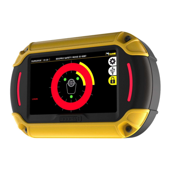
Page 136: Display
DATA SHEET OF THE COMPONENTS OF THE SYSTEM 25.6 DISPLAY Code P LX SAFEMOVE DIS By means of visual and sound alarms, the Display warns the driver, in real time, about the presence and position of pedestrian workers/vehicles with an active Tag entering the danger areas around a vehicle in motion. The display is connected to the control unit by means of a sole 2.5m-long cable that has a bayonet connector at its end. -
Page 137: Inhibitor
DATA SHEET OF THE COMPONENTS OF THE SYSTEM 25.7 INHIBITOR Code P LX FILTER SENS The inhibitor (P LX FILTER SENS) is a device used to delimit a zone within which, in accordance with the client's safety needs defined, the Tags are temporarily disabled. This device is found in the cabin of the vehicle;... -
Page 138: Splitter
DATA SHEET OF THE COMPONENTS OF THE SYSTEM 25.8 SPLITTER Code P LX SPLITMOVE04 The splitter is an element of the system if more than three sensors are to be fitted on the vehicle. TECHNICAL SPECIFICATIONS SUPPLY VOLTAGE 12-24 V MAXIMUM POWER 0.6W OPERATING TEMPERATURE... -
Page 139: Indoor Speed Sensor
DATA SHEET OF THE COMPONENTS OF THE SYSTEM 25.9 INDOOR SPEED SENSOR Code P LX SEN AD The indoor speed sensor is a radar module to measure vehicle speed, even if there is no GPS signal. With the speed sensor, the speed signal is also received indoors since an external signal is not necessary for operation. Please, keep in mind that the speed sensor does not supply data about the vehicle position, only the speed. -
Page 140: Shocks Sensor
DATA SHEET OF THE COMPONENTS OF THE SYSTEM 25.10 SHOCKS SENSOR Code P LX SEN SK The indoor speed sensor is a radar module to measure vehicle speed, even if there is no GPS signal. With the speed sensor, the speed signal is also received indoors since an external signal is not necessary for operation. Please, keep in mind that the speed sensor does not supply data about the vehicle position, only the speed. - Page 141 The technical materials and information contained in this document are strictly confidential and the exclusive property of Advanced Microwave Engineering s.r.l. These materials and information are intended solely for the purpose designated and may not be used otherwise. It is not permitted to disclose or reproduce them in whole or in part without express written permission.
- Page 142 Exclusively to the following activities: research, development, design, manufacturing, maintenance and after-sales service of electronic systems Advanced Microwave Engineering S.r.l. Via Lucca 50-54, 50142 Florence, Italy Tel.: +39 055 73921 E-mail: info@ameol.it Website: www.ameol.it The technical materials and information contained in this document are strictly confidential and the exclusive property of Advanced Microwave Engineering s.r.l. These materials and information are intended solely for the purpose designated and may not be used otherwise.
Need help?
Do you have a question about the Safe MOVE 4.0 and is the answer not in the manual?
Questions and answers