Table of Contents
Advertisement
Advertisement
Table of Contents

Related Manuals for EGOpro Safe Move 4.0

Summary of Contents for EGOpro Safe Move 4.0
- Page 1 EGOpro Safe Move 4.0 KIT Use and Installation Manual (V04)
-
Page 2: Table Of Contents
Table of contents 1 TABLE OF REVISIONS 2 COMPLIANCE 3 SAFETY INSTRUCTIONS 3.1 DISPOSAL 3.2 LIMITATIONS FOR USE 4 INTRODUCTION 4.1 INTENDED USE 4.2 SYMBOLS 5 BASIC KIT COMPONENTS 4 SYSTEM OPERATION 4.1 PEDESTRIAN WORKER PRE-WARNING 4.2 PEDESTRIAN WORKER WARNING 4.3 VEHICLE-VEHICLE WARNING 5 PLACING TAGS 5.1 HELMET TAG FITTING... - Page 3 TABLE OF REVISIONS 7.1 V EHICLE DECELERATION AND DRIVER RESPONSE DISTANCES 7.2 S YSTEM ACTIVATION DISTANCES ETTING THE POWERS TRANSMITTED 7.3 C ALCULATING THE DISTANCE IN CASE OF VEHICLE VEHICLE COLLISION 8 TURNING-ON AND CONFIGURATION 8.1 SYSTEM TURNING-ON 8.2 CONFIGURATION 8.2.1 STEP 1 | CONFIGURATION MENU 8.2.2 STEP 2 | ENTERING THE PASSWORD 8.2.3 STEP 3 | SENSORS...
-
Page 4: Table Of Revisions
TABLE OF REVISIONS 10.7 LANGUAGE 10.8 USERS 10.8.1 ADDING/EDITING USERS 10.8.2 IMPORTING/EXPORTING USERS 11 VEHICLE-VEHICLE ANTI-COLLISION MODULE 11.1 INSTALLATION 11.2 ALARM DISPLAY 11.3 SENSORS POWER 12 WIRING DIAGRAMS 12.1 SENSOR'S CABLE ASSEMBLY 12.2 SAFE MOVE CPU CONNECTIONS 12.3 SENSOR'S HUB CONNECTIONS 12.4 SENSORS CONNECTIONS 12.5 SAFE MOVE POWER DISTRIBUTION 12.6 SAFE MOVE POWER DISTRIBUTION (HIGH VOLTAGE BATTERY) -
Page 5: Compliance
The EGOpro Safe MOVE 4.0 system does not replace the driver’s attention and judgement or need to slow down or brake in case of danger, and it does not exonerate the purchaser and the driver from adopting the usual safety procedures foreseen. -
Page 6: Introduction
4.1 INTENDED USE The EGOpro Safe MOVE 4.0 System is a safety supporting system that is used for detecting the presence of pedestrian workers and vehicles equipped with suitable devices. When any of those are detected, sound and visual signals are generated, to which the I/O that are present in the system can be associated. -
Page 7: Basic Kit Components
BASIC KIT COMPONENTS 5 BASIC KIT COMPONENTS The EGOpro Safe MOVE 4.0 basic kit consists of: ✓ P LX SAFEMOVE DIS - Display with cable (plate and joint included) ✓ P LX SAFEMOVE SENS4 - SAFE MOVE 4.0 multifunction sensor. -
Page 8: System Operation
SYSTEM OPERATION 4 SYSTEM OPERATION The Proximity Warning & Alert System solution offered by EGOpro Safe MOVE 4.0 minimises the possibilities of accidents between forklifts and pedestrians in common working areas. By means of visual and sound alarms, the system warns the driver, in real time, about the presence and position of pedestrian workers wearing an active TAG that enter the danger areas around a vehicle in motion. -
Page 9: Placing Tags
PLACING TAGS 5 PLACING TAGS 5.1 HELMET TAG FITTING To fit the PLX TAGSAFETY 03TH Tag, you first need to clean the helmet. Then, you have to suitably remove the grease from the surface with the napkin supplied. Now you can affix the Tag as shown in the figure. 5.2 WEARABLE TAG ACCESSORIES The wearable Tag is supplied together with a series of accessories that guarantee a wide range of options for wearing it. -
Page 10: Installation On The Vehicle
INSTALLATION ON THE VEHICLE 6 INSTALLATION ON THE VEHICLE 6.1 SYSTEM ARCHITECTURE The basic KIT of the EGOpro Safe MOVE 4.0 system that is installed on the vehicle consists of the following devices: ➢ 3 Sensors ➢ 1 HUB ➢ 1 CPU ➢... -
Page 11: Positioning The Control Unit (Cpu)
INSTALLATION ON THE VEHICLE The Display and the Sensors must be correctly oriented: for this reason, they are supplied with a mounting plate and a mechanical joint onto which the support that is necessary for holding the device must be fitted. The joint, which is made up of 2 U-shaped mechanical parts, has been designed to be easily connected to the plate that is present on the devices. -
Page 12: Positioning The Display
INSTALLATION ON THE VEHICLE 6.2.2 Positioning the Display ’ ’ The Display must be positioned inside the driver s cabin in accordance with the driver s visibility requirements and taking into account the CPU position: the connection cable between Display and CPU is 2.5 m long. When installing the Display and passing the connection cable, attention must be paid so that they do not ’s ’... -
Page 13: Positioning The Hub
INSTALLATION ON THE VEHICLE Front sensors must have a small orientation towards the outside. For example, for a counterbalanced vehicle, they must be positioned outside the shape of the fork/gripper holder mounting, and they must have an orientation angle towards the outside of around 20°. -
Page 14: Connections
INSTALLATION ON THE VEHICLE 6.3 CONNECTIONS 6.3.1 General instructions The necessary connections on the systems can be summarised in two categories: ➢ Data Connections ➢ Power Supply Connections Data Connections The data connection between the system devices is established with a UTP cable. As a minimum requirement, it is recommended to use a UTP cable belonging to category 5E or above. - Page 15 INSTALLATION ON THE VEHICLE Power Supply Connection The system must be powered in direct current (VDC) ranging from 12V to 24V (±10%). The devices to be powered are the CPU and the HUB. A direct positive wire (V ) and a positive wire under key (V ) must arrive to the CPU, whereas only the direct positive wire must arrive to the HUB.
-
Page 16: Cpu Wiring
INSTALLATION ON THE VEHICLE 6.3.2 CPU Wiring The CPU is powered at 12-24V, and it needs a specific +V line (under ignition key). The CPU remains turned on even when the vehicle is off in low consumption regime (stand-by). Activation takes place when voltage is supplied to the V terminal. -
Page 17: Connecting Sensors
INSTALLATION ON THE VEHICLE 6.3.3 Connecting sensors The sensors are connected to the HUB with UTP cables with 8 poles. The maximum connection length is related to the supply voltage and the type of cable used AWG 26 AWG 24 12 V 24 V Figure 1 Maximum length of the HUB sensors connection cables according to the type of cable and the power supply... - Page 18 INSTALLATION ON THE VEHICLE The device is powered in direct current with a voltage between 12/24 V. The power supply to the device must be limited to a maximum of 3A. Use a T 3 A 125 V L fuse directly fitted on the positive-pole conductor or a 3A 32V automotive fuse. We recommend to keep the coaxial antenna cable far from the zone marked with the...
-
Page 19: Installing The System With M12 Connectors
INSTALLATION ON THE VEHICLE 6.4 INSTALLING THE SYSTEM WITH M12 CONNECTORS The PLX SAFEMOVE SENS 4 and PLX SAFEMOVE HUB 4 devices are available in a version fitted with M12 connectors. Such version has been designed in order to make the system installation and removal simpler and quicker. The table below summarises the codes used in the system fitted with connectors. -
Page 20: Length Of Connections
INSTALLATION ON THE VEHICLE Colour Function FEMALE (FRONT VIEW) Brown Blue White Green Pink Normally Open Relay1 Yellow Common Relay1 Black Normally Closed Relay1 Grey Normally Open Relay2 Common Relay2 Violet Normally Closed Relay2 Grey Pink Not Used Red Blue Not Used 6.4.1 LENGTH OF CONNECTIONS The cables supplied are 5 m long, and they are AWG 24. -
Page 21: Stopping Distances And Activation Distances
STOPPING DISTANCES AND ACTIVATION DISTANCES 7 STOPPING DISTANCES AND ACTIVATION DISTANCES When installing a safety supporting system to be used for reducing the risk of man-vehicle and vehicle-vehicle collisions, it is necessary to take into account which activation distances have to be considered for the system operation. The purpose of this is to adjust the system so that a truly helpful signal can be provided to the driver. - Page 22 STOPPING DISTANCES AND ACTIVATION DISTANCES 10.0 10.9 11.8 12.8 13.8 14.8 10.1 15.9 10.9 17.0 11.8 18.2 12.7 19.3 Chart 2 Calculation of stopping distance as per ISO 6292 A2 (<16000 kg) Speed Deceleration distance Driver reaction Total braking [km/h] [m] ISO6292 A2 distance @1s [m] distance [m]...
-
Page 23: System Activation Distances . Setting The Powers Transmitted
STOPPING DISTANCES AND ACTIVATION DISTANCES 7.2 System activation distances. Setting the powers transmitted The paragraph above dealt with how to calculate stopping distances for an industrial vehicle. When estimating the distances at which a tag potentially in danger of collision should be detected, a distance margin should be considered as well. -
Page 24: Calculating The Distance In Case Of Vehicle-Vehicle Collision
STOPPING DISTANCES AND ACTIVATION DISTANCES Long range distance-power law Power (%) Short range distance-power law Power (%) 7.3 Calculating the distance in case of vehicle-vehicle collision. In case of vehicle-vehicle collision, we can consider that the same assessments described in the paragraphs above are applicable. -
Page 25: Turning-On And Configuration
TURNING-ON AND CONFIGURATION 8 TURNING-ON AND CONFIGURATION 8.1 SYSTEM TURNING-ON The system turning-on is automatic with the connection to the power supply (12/24V ). While the system is turned on for the first time, the initialisation screen is displayed. Once initialisation is completed, the following screen is showed. The first time the system is turned on takes more time. -
Page 26: Configuration
TURNING-ON AND CONFIGURATION 8.2 CONFIGURATION In order for sensors to be recognised by the system, they must be configured from the configuration menu via the touchscreen. The following procedure describes the steps to be followed in order to configure the system and make sure that the peripheral devices are correctly connected. -
Page 27: Step 3 | Sensors
TURNING-ON AND CONFIGURATION 8.2.3 STEP 3 | SENSORS The first screen when accessing the configuration menu is the following one. To configure the sensors press the SENSORS key. To configure the sensors press the SENSORS SEARCH key. The technical materials and informations contained in this document are strictly confidential and exclusive prope rty of Advanced Microwave Engineering s.r.l. These materials and informations are intended solely for the purpose designated and may not be used otherwise. -
Page 28: Step 4 | Sensors Search
TURNING-ON AND CONFIGURATION 8.2.4 STEP 4 | SENSORS SEARCH Each sensor has an unequivocal ID that must be saved on the CPU: first perform the ID SEARCH and then the SENSORS SEARCH. Before making the ID SEARCH, make sure that the selectors present on the HUB and on each sensor are positioned on 0. -
Page 29: Step 5 | Searching Sensors By Id
TURNING-ON AND CONFIGURATION 8.2.5 STEP 5 | SEARCHING SENSORS BY ID The search sensors by ID function is used to associate each sensor ID (unequivocal Factory Code assigned by the manufacturer) with a number from 1 to 8 that is necessary for the subsequent system calibration operations. Press the SEARCH STARTING key to display all the sensors connected to the system. - Page 30 TURNING-ON AND CONFIGURATION If some sensors have not been identified, try repeating the search operation. If it still fails, check: • Position of all selectors (they must be on 0) • Connections between sensor and HUB. If no sensor is identified, check: •...
- Page 31 TURNING-ON AND CONFIGURATION If the allocation procedure has been successful, the sensors turn green and the associated IDs move to the new positions. In case of error, try making the allocation again. Press BACK and return to the previous screen. The technical materials and informations contained in this document are strictly confidential and exclusive prope rty of Advanced Microwave Engineering s.r.l.
-
Page 32: Step 6 | Searching Sensors By Position
TURNING-ON AND CONFIGURATION 8.2.6 STEP 6 | SEARCHING SENSORS BY POSITION This step checks the correct operation of the sensors and saves them to the system. Press SENSORS SEARCH (STEP 4 screen). The search for sensors starts automatically. If the ID search has been correctly performed, the selected sensors (e.g. 2, 5 and 8) will turn yellow. Press the SAVE SETTINGS key: the colour of the sensors will change from yellow to green, and, as of that moment, the sensors will be associated to the vehicle. -
Page 33: Searching Sensors Without Id
TURNING-ON AND CONFIGURATION 8.2.7 SEARCHING SENSORS WITHOUT ID A fixed position can be assigned to the sensors without making the ID search. In this case, place the selector present on each sensor in the desired position. For example, for the basic kit: •... -
Page 34: Test
TURNING-ON AND CONFIGURATION 8.3 TEST Once the sensors have been configured and saved on the system, make a test to check the system correct operation. In general, the system is working correctly if the central part of the monitor is no longer red. 8.3.1 SENSOR CHECK All sensors are in good working order if they are all green. -
Page 35: Tag Detection Test
TURNING-ON AND CONFIGURATION 8.3.2 TAG DETECTION TEST Move a Tag close to each of the sensors installed and check their operation. The transponder detection in Pre-Warning is yellow. The yellow sectors correspond to the sensor that has detected the Tag and indicate the Tag position with respect to the vehicle. The transponder detection in Warning is red. -
Page 36: Operation Modes
9 OPERATION MODES 9.1 DISPLAY OVERVIEW Main screen of EGOpro Safe MOVE 4.0 with 3 sensors installed without any detection of pedestrian workers or vehicles. In addition, the following elements are also displayed on the screen: 1. Date and time 2. -
Page 37: Pedestrian Worker's Tag Display Alarm: Pre-Warning
OPERATION MODES 9.2 PEDESTRIAN WORKER’S TAG DISPLAY ALARM: PRE-WARNING The presence of the pedestrian worker wearing an active TAG within the PRE-WARNING activation range is signalled to the driver via the display that shows the position of the pedestrian worker around the vehicle. Lighted up sectors are associated to the sensor and they are coloured according to the sensor detecting the Tag, and so ’... -
Page 38: Pedestrian Worker's Tag Display Alarm: Warning
OPERATION MODES 9.3 PEDESTRIAN WORKER’S TAG DISPLAY ALARM: WARNING The presence of the pedestrian worker wearing an active TAG within the WARNING activation range is signalled to the driver via the display by means of a clearly visible red ring. The PRE-WARNING alarm indication remains visible and helps the driver locate the personnel on foot. -
Page 39: Sensors And Hub Diagnosis
OPERATION MODES 9.4 SENSORS AND HUB DIAGNOSIS Active sensors are displayed matching their position on the vehicle. Only installed and configured sensors are shown on the display. The system is equipped with a self-diagnosis system that constantly checks the correct operation of sensors. If the icon of the sensor is GREEN, it means that the sensor is working properly. -
Page 40: Driver Login
OPERATION MODES 9.5 DRIVER LOGIN The LOGIN operation is used to check which operator is driving the vehicle at the date and time requested, and it is essential to exclude the driver’s TAG from the Proximity Warning & Alert System. When the system is turned on, the main interface presents a lateral red message inviting the user to LOGIN, which is signalled by a yellow icon. - Page 41 OPERATION MODES For the login operation, enter the unique ID in the space: USERCODE: unique numerical code of 6 digits: the code usually coincides with the TAG own code. Use the numerical keyboard to enter the code To delete only one character: To delete all characters together: Once the code has been entered, press OK.
-
Page 42: Data Access
OPERATION MODES 9.6 DATA ACCESS Press the key with the USB icon and enter the relative password to access the data page in which the history of events is shown. Up to 1,000 events can be displayed, including: • TAGS detected with the following information: detected TAG code - activated sensor - date and time - position (if the GPS module is enabled) •... -
Page 43: Basic Configuration
BASIC CONFIGURATION 10 BASIC CONFIGURATION 10.1 ACCESS TO MENU Press the CONFIGURATION icon to access the menu To access the system configuration section, a password must be entered so that only the enabled user can view this screen. The default password is 1234. The technical materials and informations contained in this document are strictly confidential and exclusive prope rty of Advanced Microwave Engineering s.r.l. -
Page 44: Reboot
BASIC CONFIGURATION 10.2 REBOOT To reboot or stop the system, enter the specific password and open the configuration menu. CLOSE key to reboot the system. If necessary, press this key to reboot the system. This key is show in all the configuration screens If the system is turned off, you will need to disconnect and reconnect power to restart it. -
Page 45: Configuration Menu
BASIC CONFIGURATION 10.3 CONFIGURATION MENU In the configuration menu, you can: • Set the system Time and Date • Configure the Modes of the alarms • Configure the sensors (System Calibration) • Select the language preferred • Set the master data of users/drivers •... -
Page 46: Clock & Date
BASIC CONFIGURATION 10.4 CLOCK & DATE Press the CLOCK AND DATE icon to access the settings 10.4.1 MANUAL In manual mode, the internal clock of the system must be set by filling in all the fields manually. On the display, touch the field to be changed and use the numerical keyboard located on the right to delete the old value and set the new one. -
Page 47: Automatic
BASIC CONFIGURATION 10.4.2 AUTOMATIC In automatic mode, the internal clock of the system becomes automatically synchronised by means of the network (if available) or the GPS module if installed. Use the side arrows to scroll the list and select the correct time zone, the system will update the time automatically. 1. -
Page 48: Alarm Configuration
BASIC CONFIGURATION 10.5 ALARM CONFIGURATION Press the ALARM CONFIGURATION icon to access the settings In the interface, the alarm modes are set. 1. VOLUME LEVEL Press keys to increase or decrease the volume of the loudspeaker. • ‘ ’ Press Audio Test to start a test (the Tag In sound and the Tag Stay sound will be reproduced consecutively). - Page 49 BASIC CONFIGURATION The five alarm modes are summarised in the table below: ALARM MODES SOUND ALARM TAG LAST TIME THAT THE TIME THAT THE REPETITION TIME (S) RECEPTION TIME (S) ALARM REMAINS IN ALARM REMAINS IN VIDEO (S) THE LISTS (S) 1000 3.
-
Page 50: Sensors Configuration
BASIC CONFIGURATION 10.6 SENSORS CONFIGURATION Press the SENSORS CONFIGURATION icon to access the settings The sensors configuration menu includes 4 STEPS: 1. Sensors Search Tool to detect and save the sensors installed. 2. Sensors Power Tool to set the system operating range. 3. -
Page 51: Sensors Power
BASIC CONFIGURATION 10.6.2 SENSORS POWER Press the SENSORS POWER icon to access the settings • Select LR SENSORS POWER to configure the Pre-warning alarm range • Select SR SENSORS POWER to configure the Warning alarm range Before adjusting the system power, carefully read chapter 7: STOPPING DISTANCES. The technical materials and informations contained in this document are strictly confidential and exclusive prope rty of Advanced Microwave Engineering s.r.l. -
Page 52: Lr Sensors Power
BASIC CONFIGURATION 10.6.3 LR SENSORS POWER Adjust the LR sensor power to change the Tag, and so the pedestrian worker, detection distance in the Pre-Warning area. In order to change the power of sensors: • Select the sensor by pressing the corresponding icon: the selection will be highlighted by a green ring around the icon. -
Page 53: Sr Sensors Power
BASIC CONFIGURATION 10.6.4 SR SENSORS POWER Adjust the SR sensor power to change the Tag, and so the pedestrian worker, detection distance in the Pre-Warning area. In order to change the power of sensors: • Select the sensor by pressing the corresponding icon: the selection will be highlighted by a green ring around the icon. -
Page 54: Wi-Fi Channels
BASIC CONFIGURATION 10.6.5 WI-FI CHANNELS Press the WI-FI CHANNELS icon to access the settings The system operation frequency can be set according to the configuration of the Wi-Fi network where the system is installed. The basic system signals: • In red, channels 1-6-11 (those mostly used) that are considered busy by default •... -
Page 55: Wi-Fi Channels: Automatic Selection
BASIC CONFIGURATION 10.6.6 WI-FI CHANNELS: AUTOMATIC SELECTION With the Automatic Selection mode, the operating frequency of the sensors is set automatically taking into account the channels, in the 2.45 GHz band, already taken by other systems that were entered into the section of the busy channels. Before pressing the key for the automatic selection of the Wi-Fi channels, go to the section of the busy channels to select the non-available channels. -
Page 56: Wi-Fi Channels: Manual Selection
BASIC CONFIGURATION 10.6.7 WI-FI CHANNELS: MANUAL SELECTION In manual mode, the operating frequency can be selected along the entire 2.45 GHz band no matter if the channels are busy or not. Press the keys to increase or decrease the operating frequency. •... -
Page 57: Tag Settings
BASIC CONFIGURATION 10.6.8 TAG SETTINGS When a pedestrian worker wearing an active PPE enters into a dangerous area around a vehicle, the TAG will be activated and a warning sound with adjustable intermittence will be triggered. ’ Tag Settings express in second(s) the time that elapses between a sound alarm and the other on the user s Tag, when it is in the detection range of a sensor. - Page 58 BASIC CONFIGURATION 10.7 LANGUAGE Press the corresponding key to select the language chosen. These are the settable languages: 1. Italian 2. English 3. French 4. Spanish The technical materials and informations contained in this document are strictly confidential and exclusive property of Advanced Microwave Engineering s.r.l. These materials and informations are intended solely for the purpose designated and may not be used otherwise.
- Page 59 BASIC CONFIGURATION 10.8 USERS The Users section shows the codes of the Tags that were entered into the system master data for login and logout (paragraph 9.5). ’ To change the master data and see the users codes, log in as an administrator. The default code for administrators is 9999.
- Page 60 BASIC CONFIGURATION 10.8.1 ADDING/EDITING USERS Fill in the following boxes for master data to add or edit a user: ‘ ’ User code Enter the code to be associated to the Tag to be used to log in. The user code will be the code saved and displayed in the file of events.
- Page 61 ‘ ’ Upload Config. This is used to import the list of users from a USB key. Before importing all the data of users, they will be deleted from the database of the EGOpro Safe Move system. ‘ ’ ‘...
- Page 62 BASIC CONFIGURATION • DATE MODIFY: date in the dd/MM/yyyy format [NOT MANDATORY] • LAST LOGIN: date in the dd/MM/yyyy format [NOT MANDATORY] • CODE TAG: max. 6 figures, numerical [NOT MANDATORY] • CODE BADGE: alphanumeric [NOT MANDATORY] NOTES: • The username field must be univocal, and it is used to log in. •...
- Page 63 In this case, there are three visual alarms: • WHITE: it warns about the presence of other vehicles equipped with the EGOpro Safe MOVE system in a dangerous area around the vehicle. The direction from which the other vehicle is coming is indicated by the sectors.
- Page 64 VEHICLE-VEHICLE ANTI-COLLISION MODULE 11.3 SENSORS POWER ’ ’ In this section, the sensor power, and thus the detection distance of both the pedestrian worker s Tag and the vehicle Tag, can be changed. ’ ‘ ’ To configure the sensor power with respect to the vehicle s Tag, press the VEHICLE key, and carry out all the same...
- Page 65 WIRING DIAGRAMS 12 WIRING DIAGRAMS 12.1 SENSOR'S CABLE ASSEMBLY The technical materials and informations contained in this document are strictly confidential and exclusive prope rty of Advanced Microwave Engineering s.r.l. These materials and informations are intended solely for the purpose designated and may not be used otherwise. It is not permitted to disclose or reproduce in whole or in part without express written permission.
- Page 66 WIRING DIAGRAMS 12.2 SAFE MOVE CPU CONNECTIONS The technical materials and informations contained in this document are strictly confidential and exclusive property of Advanced Microwave Engineering s.r.l. These materials and informations are intended solely for the purpose designated and may not be used otherwise. It is not permitted to disclose or reproduce in whole or in part without express written permission.
- Page 67 WIRING DIAGRAMS 12.3 SENSOR'S HUB CONNECTIONS 12.4 SENSORS CONNECTIONS The technical materials and informations contained in this document are strictly confidential and exclusive prope rty of Advanced Microwave Engineering s.r.l. These materials and informations are intended solely for the purpose designated and may not be used otherwise. It is not permitted to disclose or reproduce in whole or in part without express written permission.
- Page 68 WIRING DIAGRAMS 12.5 SAFE MOVE POWER DISTRIBUTION The technical materials and informations contained in this document are strictly confidential and exclusive property of Advanced Microwave Engineering s.r.l. These materials and informations are intended solely for the purpose designated and may not be used otherwise. It is not permitted to disclose or reproduce in whole or in part without express written permission.
- Page 69 WIRING DIAGRAMS 12.6 SAFE MOVE POWER DISTRIBUTION (HIGH VOLTAGE BATTERY) The technical materials and informations contained in this document are strictly confidential and exclusive prope rty of Advanced Microwave Engineering s.r.l. These materials and informations are intended solely for the purpose designated and may not be used otherwise. It is not permitted to disclose or reproduce in whole or in part without express written permission.
- Page 70 DATA SHEET OF SYSTEM COMPONENTS 13 DATA SHEET OF SYSTEM COMPONENTS 13.1 SENSOR Code PLX SAFEMOVE SENS 4 The Sensor is positioned around the vehicle, and generates 2 alarm/detection areas around the vehicle: • Pre-Warning up to 50 m • Warning up to 5 m The sensor also detects the presence of other vehicles in the Pre-Warning area up to 100 m.
- Page 71 DATA SHEET OF SYSTEM COMPONENTS 13.2 HUB Code PLX SAFEMOVE HUB 4 The HUB is the device in charge of managing the sensors. It has a communication connection towards the CPU and 3 connections towards the sensors. The number of sensors managed can be extended up to 8 with suitable expansion devices.
- Page 72 Use the screws supplied: 2.2X7 With the wearable Tag, pedestrian workers can be detected by the EGOpro Safe MOVE 4.0 system either in Pre-Warning or in Warning. The Tag is powered by a lithium button cell battery that is easy to replace.
- Page 73 DATA SHEET OF SYSTEM COMPONENTS 13.4 HELMET TAG Code PLX TAGSAFETY 3TH The helmet Tag has the same functions as the wearable Tag, but it has been designed to be affixed to safety helmets. It uses two-antenna architecture for Pre-Warning located inside flexible wings fitted with suitable adhesive for polyethylene and HD polyethylene, the material with which safety helmets are made.
- Page 74 P LX SAFEMOVE CPU The CPU of the EGOpro Safe Move 4.0 system is the core of the system. All devices must be connected to a CPU via a Data Bus. It manages everything related to configurations, data logging and the activation of other functions compatible with the system (e.g., speed reduction).
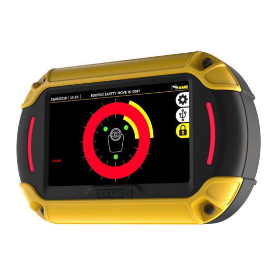
- Page 75 DATA SHEET OF SYSTEM COMPONENTS 13.6 DISPLAY Code P LX SAFEMOVE DIS By means of visual and sound alarms, the Display warns the driver, in real time, about the presence and position of pedestrian workers/vehicles with an active Tag entering the danger areas around a vehicle in motion . The display is connected to the control unit by means of a sole 2.5m-long cable that has a bayonet connector at its end.
- Page 76 DATA SHEET OF SYSTEM COMPONENTS Exclusively to the following activities: research, development, design, creation, maintenance and post-sales assistance of electronic systems Advanced Microwave Engineering S.r.l. Via Lucca 50-54, 50142 Florence, Italy Tel.: +39 055 73921 - E-mail: info@ameol.it Web: www.ameol.it The technical materials and informations contained in this document are strictly confidential and exclusive property of Advanced Microwave Engineering s.r.l.
Need help?
Do you have a question about the Safe Move 4.0 and is the answer not in the manual?
Questions and answers