
Related Manuals for WLKATA Mirobot

Summary of Contents for WLKATA Mirobot
- Page 1 WLKATA Mirobot manipulator User Manual WLKATA Mirobot User Manual Version: 1.2 Date: May 30th 2020 Beijing Tsinew Technologies Co., Ltd. 北 京 勤 牛 创 智 科 技 有 限 公 司 www.wlkata.com...
- Page 2 Tsinew Technology recommends that you use this manual under the guidance of professionals. All safety information contained in this manual shall not be regarded as the guarantee of Mirobot. Even if the manual and relevant instructions are followed, the hazards or losses caused in the use process may still occur.
- Page 3 WLKATA Mirobot Manipulator User Manual Preface Objective This manual introduces the functions, technical specifications, installation instructions, system debugging, etc. Informal writing of the Mirobot manipulator, which is convenient users understand and use the Mirobot manipulator. Readers This manual applies to: ...
- Page 4 WLKATA Mirobot Manipulator User Manual Symbolic conventions The following symbols may appear in this manual, and their meanings are as follows. Symbol Explain Indicates a high potential hazard which, if not avoided, could result in personnel death or severe injury.
-
Page 5: Table Of Contents
WLKATA Mirobot Manipulator User Manual Table of Contents Introduction of WLKATA Mirobot ............. 7 Structure of WLKATA Mirobot ..............7 Items in the WLKATA Mirobot standard set ..........9 Add-ons and accessories ................9 Safety precautions .................. 10 General Safety ..................11 Precautions .................... - Page 6 Interface board of the Extender Box ............58 Appendix I ....................60 WLKATA Mirobot Calibration Operation ............60 Appendix II ....................62 Trouble shooting list of WLKATA Studio and Mirobot ........62 Document version 1.0 User Manual Copyright© Beijing Tsinew Technologies Co., Ltd.
-
Page 7: Introduction Of Wlkata Mirobot
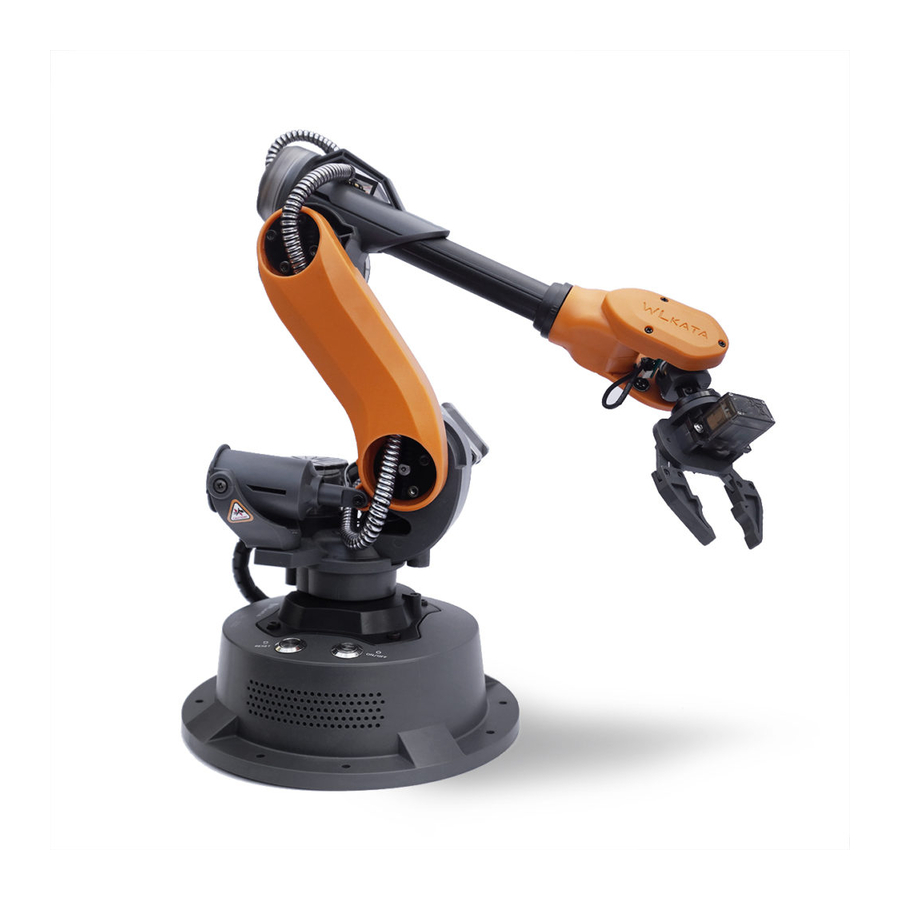
Figure 1.1. There are a total of six robot joints in Mirobot, please see Figure 1.2 to familiar with the name of each of the six joints. The reference frame is shown in Figure 1.3. For more information of the structure of Mirobot, please refers to 4 Working principle and specification in this manual. - Page 8 WLKATA Mirobot Manipulator User Manual Figure 1.2 The Six Joint Frame Of WLKATA Mirobot Figure 1.3 Reference Frame of WLKATA Mirobot Document version 1.0 User Manual Copyright© Beijing Tsinew Technologies Co., Ltd.
-
Page 9: Items In The Wlkata Mirobot Standard Set
The WLKATA Mirobot standard set is ready for users who want to experience the essential functions of the Mirobot. There are 10 items in the standard set package, including the Mirobot manipulator, User Manual (paper-based simplified version), Bluetooth Box, Extender Box, IDC Cable, Gripper Module, Pen Holding, Power Supply, USB Cable and Hex Screwdrivers. -
Page 10: Safety Precautions
Robot Arm Vehicle Robot Arm Vehicle Power Supply and Battery Figure 1.5 Add-ons and accessories for the WLKATA Mirobot 2 Safety precautions This chapter introduces the safety precautions when using this device. Please read this manual carefully before using the manipulator for the first time. This device should be used in an environment that meets the below requirements. -
Page 11: General Safety
It is not suggested to repair the faulty parts or dismantle the manipulator without professional training. If the devices fail, please contact the WLKATA Mirobot technical support engineer for advices. The high corrosive cleaning is not suitable for the cleaning of the manipulator, and the anodized parts are not suitable for immersion cleaning. -
Page 12: Precautions
Always remember to lift and handling Mirobot by holding the Lower Arm with one hand and holding the Base with the other hand. One should not lift or handle Mirobot by holding the Upper Arm, or it would cause a damage to the motor gears of the major joints. - Page 13 DO NOT (!) twist the Joint 1 or Joint 3 by hand in any case, since this would lead to a fetal damage to these joints (due to the high reduction gear ratio of these motors). It is only allowed to adjust the joints by using WLKATA studio or proper operation software.
- Page 14 WLKATA Mirobot Manipulator User Manual IV. Caution the Hot Surface of Motor & Chip When Mirobot is powered on, DO NOT (!) touch the surface of joint 6 motor or the chip by hand, as those parts could be very hot during working.
- Page 15 Mirobot manipulator Each Time the manipulator is powered on, RESET from an emergency stop, or reopen the WLKATA studio, the user must execute the HOMING action by click the HOMING button in WLKATA Studio to homing the joints position.
-
Page 16: Quick Start
Figure 3.1 The quick start flow chart of using WLKATA Mirobot manipulator 3.1 Power adapter and USB cable connection (1) Use the supplied USB data cable to connect the WLKATA Mirobot and your computer. As shown in the Figure 3.2 Figure 3.2 Connecting the manipulator to the computer... -
Page 17: Installing The Driver And Wlkata Studio
Figure 3.3 Connecting the manipulator to the power adapter 3.2 Installing the driver and WLKATA Studio The users can control the Mirobot by using WLKATA Studio software to realize functions such as Joint Mode control, Coordinate Mode control, Teaching & Play, Blockly control and Drawing, etc. - Page 18 WLKATA Mirobot Manipulator User Manual Figure 3.4 CH340 driver installation wizard interface Figure 3.5 Driver installed successfully 2.Verifying the driver (1) Ensure to connect the manipulator to the computer by using the supplied USB data cable. (2) Open the Device Manager in your PC windows system. Ensure to tick the Show hidden devices option in the View menu.
-
Page 19: Installing And Verification Of Wlkata Studio
Figure 3.6 Serial port drive information of the WLKATA Mirobot manipulator Installing and verification of WLKATA Studio 1. Installing WLKATA Studio WLKATA Studio software package can be directly decompressed and used, as shown in Figure 3.7. Decompress the WLKATA Studio software package to... - Page 20 Figure 3.8 WLKATA Studio interface 2.Verifying WLKATA Studio Software In the decompressed package, double-click to open the Wlkata studio.exe. If the Wlkata Studio software can be opened correctly, it means that the WLKATA Studio software is running successfully. Document version 1.0 User Manual Copyright©...
- Page 21 (1) Open the Wlkata Studio.exe. The software should automatically search and connect to the manipulator after a few seconds. When successfully connects to the manipulator, the upper left corner of the WLKATA Studio interface should display the CONNECTED blue icon, as shown in Figure 3.9.
-
Page 22: Powering On And Off Wlkata Mirobot
WLKATA Studio software. Prerequisite • The driver and WLKATA Studio software have been installed successfully. For details, please refer to the 3.2 Installing the driver and WLKATA Studio software. • The manipulator has been correctly connected to the computer, and the power supply Document version 1.0... -
Page 23: Preparing Operation Steps
WLKATA Mirobot Manipulator User Manual of the manipulator has been turned on. Please refer to 3.3 Powering on and off WLKATA Mirobot for detailed operation. Preparing operation steps 1. Connecting WLKATA studio with the manipulator Double click the Wlkata Studio.exe in the directory, and the Mirobot Studio interface should pop up. - Page 24 In case of any illegal operation of the manipulator, click the STOP button immediately in the Mirobot Studio to trigger a software emergency stop operation, as shown in the Figure 3.15. After the emergency stop operation, press the RESET button on the top of the manipulator base to recover the device from the emergency status, as shown in Figure 3.16.
-
Page 25: Using The Robot Joint Mode Control Function
WLKATA Mirobot Manipulator User Manual Figure 3.15 Emergency stop button in the WLKATA Studio Figure 3.16 Pressing RESET button on the base of the manipulator after a software emergency stop Using the ROBOT JOINT MODE control function (1) Click the COMMAND tab in the software interface, as shown in Figure 3.17. -
Page 26: Using The Coordinate Mode Control Function
WLKATA Mirobot Manipulator User Manual (2) Switch to the ROBOT JOINT MODE in the upper-right control modes selection panel, as shown in Figure 3.18. Figure 3.18 Selecting the ROBOT JOINT MODE (3) Click each of the J+ J- control buttons on the right panel to control the motion of each of the six joints of the manipulator separately. -
Page 27: Using The Teaching Function
WLKATA Mirobot Manipulator User Manual Figure 3.20 Selecting the COORDINATE MODE (3) Click each of the control button on the right panel of the WLKATA Studio to control the spatial position and attitude (XYZ coordinate and RPY angle) of the End-effector of the manipulator. - Page 28 PLAY file/task, or the point data after switching the mode would be discordant and cause illegal motions. (3) Click the - + control buttons on the right panel of WLKATA Studio to move the joints (under the ROBOT JOINT MODE) / or the position and attitude of the End-effector (under the COORDINATE MODE) to the wanted position.
- Page 29 WLKATA Mirobot Manipulator User Manual Figure 3.23 Adding the teaching points under the TEACHING page (4) After adding the first teaching point, one could continue to adjust the position and posture of the manipulator, and then click the Add Point button to add the second and the third teaching point...
-
Page 30: Using The Blockly Function
Teaching & Play task, click Save and save the task in chosen directory. To open a Teaching & Play file created by WLKATA Studio earlier, click Open to lookup the file. (7) Click Move down and Move up buttons to change the order of a teaching point line. -
Page 31: Using The Gripper Module
Blockly task, click Save and save the task in chosen directory. To open a Blockly file created by WLKATA Studio earlier, click Open to lookup the file. To delete a module, select the module and click the Trash icon. - Page 32 (4) Plug the gripper wire connector into the upper-second socket position (GRIPPER) on the Extender Box unit, as shown in Figure 3.30. (5) Link the Extender Box with the Mirobot by using the supplied IDC cable, as shown in Figure 3.30.
- Page 33 WLKATA Mirobot Manipulator User Manual (4) Control the gripper status (open and close): The gripper can be controlled under the COMMAND, TEACHING and BLOCKLY functions in the WLKATA Studio: • In the COMMAND page, control the gripper by click the End-effect on and End-effector off buttons on the right panel.
-
Page 34: Using The Drawing Function
Using the DRAWING function Helping Us to Make the Drawing Function Better The Drawing function of WLKATA Mirobot is still in development. Users may encounter inconvenience during operation. Please provide us your valuable feedback in the Facebook WLKATA fans club or in our website forum. - Page 35 Please follow the below instruction: • In the WLKATA Studio software, click the COMMAND tab in the software interface to switch to the Command page. • Choose the COORDINATE MODE in the control modes selection panel. So that the Set Pen Height button is shown in the lower position of right panel.
- Page 36 WLKATA Mirobot Manipulator User Manual Figure 3.36 Setting the pen height before drawing Letting the manipulator draw (7) Click the DRAWING tab in the software to switch to the drawing page. (8) To add a graph from existing files, you can either choose an example from the upper right panel 2 Examples, or insert a graph by click Insert button.
- Page 37 WLKATA Mirobot Manipulator User Manual (9) To add a text graph, typing in the lower right panel 3 and click Add button, and the text you have typed should be placed in the center canvas, as shown in Figure 3.37.
- Page 38 WLKATA Mirobot Manipulator User Manual Figure 3.38 Switching from Select mode to Pen mode to draw by mouse Figure 3.39 Drawing by WLKATA Mirobot Document version 1.0 User Manual Copyright© Beijing Tsinew Technologies Co., Ltd.
-
Page 39: Using The Pneumatic Set
(5) Plug the other end of the wire connector into the Pneumatic Unit. (6) Link the air pipe on the Pneumatic Unit with the metal air outlet on the pneumatic tool. (7) Link the Extender Box with the Mirobot by using the supplied IDC cable, as shown in Figure 3.40. - Page 40 WLKATA Mirobot Manipulator User Manual (8) Control the pneumatic tool status (suction cup on and off): The pneumatic tool can be controlled under the COMMAND, TEACHING and BLOCKLY functions in the WLKATA Studio: • In the COMMAND page, control the pneumatic tool by click the End-effect on and End-effector off buttons on the right panel.
-
Page 41: Using The Teach Pendant (Bluetooth Controller)
Mirobot desktop robotic arm. It supports each axis control mode, Cartesian control mode and teaching record mode. After the Mirobot robotic arm is connected to the Bluetooth teach pendant, you can use this teach pendant to control the movement of the Mirobot robotic arm, which is convenient for users to understand and use the Mirobot robotic arm. - Page 42 WLKATA Mirobot Manipulator User Manual 3.5.2.2 Teach pendant control page composition and main function description The Mirobot teach pendant is mainly composed of angle mode, coord. mode, record and setting function pages. (1)Angle Mode page The angle mode page is mainly responsible for the motion control of each axis of the manipulator.
-
Page 43: Operation Guide
WLKATA Mirobot Manipulator User Manual Figure3.43 Record page and button function description (2)Setting page The setting page is mainly responsible for the speed control of the manipulator and Bluetooth connection. Figure3.44 Setting page and button function description Operation Guide 3.5.3.1 Power ON/OFF Press and hold the power button on the Bluetooth teach pendant for three seconds to open the teach pendant. - Page 44 (1)Connect the Bluetooth extension module and the communication extension interface on the back of the Mirobot manipulator base, as is shown in Figure 3.46. Figure3.46 The connection between Bluetooth extension module and Mirobot manipulator (2)Turn on the power of the manipulator. At this time, the red LED on the Bluetooth extension module starts to flash, indicating that it is waiting for the Bluetooth teach pendant to connect.
- Page 45 WLKATA Mirobot Manipulator User Manual Led-Green Led-Red Figure3.47 LED light on Bluetooth expansion module (3)Switch the control page tab on the teach pendant to the setting page, as is shown in Figure 3.48. Figure3.48 Setting page on Bluetooth teach pendant (4) Click the “Search”...
- Page 46 WLKATA Mirobot Manipulator User Manual Figure3.49 Link button 3.5.3.3 Example of using the teach pendant single axis angle mode to control the robotic arm (1)Switch the Bluetooth teach pendant interface to the angle mode interface, as is shown in Figure 3.50.
- Page 47 WLKATA Mirobot Manipulator User Manual Figure3.51 Reset button (3)Press the 6 groups of buttons on the right side of the Bluetooth teach pendant to control the 6 corresponding rotating axes of the manipulator to move in the positive and negative directions, as is shown in Figure3.52.
- Page 48 WLKATA Mirobot Manipulator User Manual Figure 3.53Coor.Mode interface of Bluetooth teach pendant (2) The robotic arm needs to be reset once. Press and hold the red button on the upper right of the teach pendant for 3 seconds. The robotic arm will start to reset. Wait for the robotic arm to reset successfully before continuing the operation.
- Page 49 State 2: The outer ring lights up and enters the teaching mode Figure 3.56 Enter teaching mode (2) When the Mirobot is controlled to move to a certain position (or change the end fixture enable status) through the teach pendant, click the...
-
Page 50: Cautions And Disclaimers
Figure 3.57 Record page Cautions and Disclaimers Before using the Mirobot Bluetooth remote control, please read the product manual carefully. The operation and system developers of the Bluetooth remote control must first read the manual carefully and use this remote control strictly in accordance with the operation guide. -
Page 51: Disclaimers
WLKATA Mirobot Manipulator User Manual • If this product is discarded, please follow relevant laws to properly dispose of industrial waste and protect the environment. Disclaimers To the maximum extent permitted by law, the products described in this manual (including its hardware, software, etc.) are provided "as is"... -
Page 52: Working Principle And Specification
The workspace of WLKATA Mirobot is shown in Figure 4.1. Figure 4.1 The workspace of WLKATA Mirobot Coordinate system WLKATA Mirbot has a six-joint coordinate system and a Cartesian space coordinate system as shown in Figure 4.2 and 4.3, respectively. Document version 1.0 User Manual Copyright©... - Page 53 WLKATA Mirobot Manipulator User Manual Figure 1.2 Six-joint coordinate system Of WLKATA Mirobot Figure 1.3 Reference frame (Cartesian space coordinate system) of WLKATA Mirobot 1 Joint coordinate system: the coordinate system determined by reference to each moving joint. • This manipulator has six joints: j1 j2 J3 J4 J5 J6, all of which are rotary joints. The positive rotation direction of each joint follows the right-hand rule and the thumb points to the opposite direction of the output shaft of each shaft motor.
-
Page 54: Sports Function
WLKATA Mirobot Manipulator User Manual Sports function The motion modes of Mirobot manipulator include Joint motion mode and Coordinate mode. 1 Joint motion mode: the Joint motion mode means that each joint of the manipulator is controlled separately. You can click the joint motion button to move a single joint. -
Page 55: Technical Specifications
WLKATA Mirobot Manipulator User Manual The Cartesian motion mode supports point-to-point motion mode and linear interpolation motion mode. Please refer to the WLKATA Mirobot communication instructions for specific modes information. 4.2 Technical specifications Technical parameters Figure 4.1 Parameter specifications Parameter specification... - Page 56 WLKATA Mirobot Manipulator User Manual Axis 5 - 180 ° to + 40 ° 33° / s Axis 6 -180 ° to + 180 ° 66° / s Figure 4.3 Physical characteristics physical characteristics Net weight (manipulator and controller) 1.5kg <diameter160mm...
-
Page 57: Technical Parameters
WLKATA Mirobot Manipulator User Manual Technical parameters The size parameters of WLKATA Mirobot are shown in Figure 4.5, and the installation hole size of its end flange is shown in Figure 4.6. Figure 3.5 WLKATA Mirobot size parameters Figure 3.6 The end flange size of WLKATA Mirobot 5 Interface description 5.1 Interface board of the manipulator... -
Page 58: Interface Board Of The Extender Box
WLKATA Mirobot Manipulator User Manual The interface is located at the back of the base of the WLKATA Mirobot , and the schematic diagram of the base interface is shown in Figure 5.1. Figure 5.1 Back interface of substructure The PIN of the extended communication interface and the definition of each pin is shown in Figure 5.1. - Page 59 WLKATA Mirobot Manipulator User Manual Figure 4.4Mirobot general external interface board (Extender Box) and the Pin definition diagram Document version 1.0 User Manual Copyright© Beijing Tsinew Technologies Co., Ltd.
-
Page 60: Wlkata Mirobot Calibration Operation
WLKATA Mirobot Calibration Operation Calibration Operation Procedure: The Mirobot is calibrated before leaving the factory. In each time the manipulator finishes the HOMING action, the joint 1, joint 2, joint 3, joint 4 and joint 5 should be homed to the pre-designed homing position, as shown in Figure A1. - Page 61 WLKATA Mirobot Manipulator User Manual (1) Connect the Mirobot manipulator to the computer with USB cable, and turn on the power supply. (2) Open the Wlkata Studio.exe software interface. Ensure the WLKATA Studio shows a CONNECTED icon which indicates the manipulator is connected to the software.
-
Page 62: Trouble Shooting List Of Wlkata Studio And Mirobot
D:\ or E:\ to avoid potential foreign language character disturb. (4) Double-click Wlkata Studio.exe in the directory and start to use the WLKATA Mirobot. 2. If you want to put the mirobot back into the box, please adjust the Mirobot to the position shown below. Document version 1.0 User Manual Copyright©... - Page 63 WLKATA Mirobot Manipulator User Manual The first axis sensor failure problem (we will improve this hardware issue in the next version of WLKATA Mirobot) Cause: The sensor plug is loose or the one-axis screw is loose, resulting in the sensor not detecting the magnet.
- Page 64 WLKATA Mirobot Manipulator User Manual Document version 1.0 User Manual Copyright© Beijing Tsinew Technologies Co., Ltd.
Need help?
Do you have a question about the Mirobot and is the answer not in the manual?
Questions and answers