
Summary of Contents for WLKATA Mirobot
- Page 1 WLKATA Mirobot manipulator User Manual WLKATA Mirobot User Manual Version: 1.3 Date: Sep 30th 2020 WLKATA Robotics Beijing Tsinew Technologies Co., Ltd. 北 京 勤 牛 创 智 科 技 有 限 公 司 www.wlkata.com...
- Page 2 Tsinew Technology recommends that you use this manual under the guidance of professionals. All safety information contained in this manual shall not be regarded as the guarantee of Mirobot. Even if the manual and relevant instructions are followed, the hazards or losses caused in the use process may still occur.
- Page 3 WLKATA Mirobot Manipulator User Manual Preface Objective This manual introduces the functions, technical specifications, installation instructions, system debugging, etc. Informal writing of the Mirobot manipulator, which is convenient users understand and use the Mirobot manipulator. Readers This manual applies to: ...
- Page 4 WLKATA Mirobot Manipulator User Manual Symbolic conventions The following symbols may appear in this manual, and their meanings are as follows. Symbol Explain Indicates a high potential hazard which, if not avoided, could result in personnel death or severe injury.
-
Page 5: Table Of Contents
WLKATA Mirobot Manipulator User Manual Table of Contents Introduction of WLKATA Mirobot ............. 7 Structure of WLKATA Mirobot ............... 7 Items in the WLKATA Mirobot standard set ........... 9 Add-ons and accessories ................9 Safety precautions .................. 10 General Safety ..................11 Precautions ..................... - Page 6 WLKATA Mirobot Calibration Operation ............73 Appendix II ....................76 Mirobot Firmware Upgrade Tutorial ............... 76 Appendix III ....................78 Trouble shooting list of WLKATA Studio and Mirobot ........78 Document version 1.0 User Manual Copyright© Beijing Tsinew Technologies Co., Ltd.
-
Page 7: Introduction Of Wlkata Mirobot
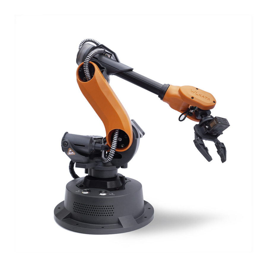
Structure of WLKATA Mirobot WLKATA Mirobot is mainly composed by a base, six rotating joints, a lower arm, an upper arm, an end-effector connection plate. There are a total of six robot joints in Mirobot. The reference frame is shown in Figure below. - Page 8 WLKATA Mirobot Manipulator User Manual The Six Joint Frame Of WLKATA Mirobot Reference Frame of WLKATA Mirobot Document version 1.0 User Manual Copyright© Beijing Tsinew Technologies Co., Ltd.
-
Page 9: Items In The Wlkata Mirobot Standard Set
The WLKATA Mirobot standard set is ready for users who want to experience the essential functions of the Mirobot. There are 10 items in the standard set package, including the Mirobot manipulator, User Manual (paper-based simplified version), Bluetooth Box, Extender Box, IDC Cable, Gripper Module, Pen Holding, Power Supply, USB Cable and Hex Screwdrivers. -
Page 10: Safety Precautions
WLKATA Mirobot Manipulator User Manual Low Power Pneumatic Unit Suction Cup 2-Finger Gripper High Power Pneumatic Unit Universal Ball Gripper GoPro (Hero7) Carrier Sliding Rail Conveyor Belt Robot Arm Vehicle Robot Arm Vehicle Power Supply and Battery 2 Safety precautions This chapter introduces the safety precautions when using this device. -
Page 11: General Safety
It is not suggested to repair the faulty parts or dismantle the manipulator without professional training. If the devices fail, please contact the WLKATA Mirobot technical support engineer for advices. The high corrosive cleaning is not suitable for the cleaning of the manipulator, and the anodized parts are not suitable for immersion cleaning. -
Page 12: Precautions
Always remember to lift and handling Mirobot by holding the Lower Arm with one hand and holding the Base with the other hand. One should not lift or handle Mirobot by holding the Upper Arm, or it would cause a damage to the motor gears of the major joints. - Page 13 DO NOT (!) twist the Joint 1 or Joint 3 by hand in any case, since this would lead to a fetal damage to these joints (due to the high reduction gear ratio of these motors). It is only allowed to adjust the joints by using WLKATA studio or proper operation software.
- Page 14 WLKATA Mirobot Manipulator User Manual IV. Caution the Hot Surface of Motor & Chip When Mirobot is powered on, DO NOT (!) touch the surface of joint 6 motor or the chip by hand, as those parts could be very hot during working.
- Page 15 Mirobot manipulator Each Time the manipulator is powered on, RESET from an emergency stop, or reopen the WLKATA studio, the user must execute the HOMING action by click the HOMING button in WLKATA Studio to homing the joints position.
-
Page 16: Quick Start Guide Of Mirobot
The quick start flow chart of using WLKATA Mirobot manipulator Power adapter and USB cable connection (1) Use the supplied USB data cable to connect the WLKATA Mirobot and your computer. Connecting the manipulator to the computer Document version 1.0 User Manual Copyright©... -
Page 17: Powering On And Off Wlkata Mirobot
(2) Connect the supplied power adapter to the manipulator. Connecting the manipulator to the power adapter Powering on and off WLKATA Mirobot DO NOT Twisting the Joint 1 or Joint 3 by Hand No Matter the Manipulator Is Powered On or Off! Since this would lead to a fetal damage to the gears of these joints. -
Page 18: Installing The Driver And Wlkata Studio
The power indicator light on the button will turned off. Installing the driver and WLKATA Studio The users can control the Mirobot by using WLKATA Studio software to realize functions such as Joint Mode control, Coordinate Mode control, Teaching & Play, Blockly control and Drawing, etc. - Page 19 WLKATA Mirobot Manipulator User Manual Driver installed successfully 2.Verifying the driver (1) Ensure to connect the manipulator to the computer by using the supplied USB data cable. (2) Open the Device Manager in your PC windows system. Ensure to tick the Show hidden devices option in the View menu.
-
Page 20: Installing And Verification Of Wlkata Studio
Serial port drive information of the WLKATA Mirobot manipulator Installing and verification of WLKATA Studio 1. Installing WLKATA Studio Log in to the official website: www.wlkata.com. Click "Support-Download Center". Choose "Wlkata Studio-Win-v1.015.zip (Alpha version)" to download. WLKATA Studio software package can be directly decompressed and used. - Page 21 D:\ or E:\ to avoid potential foreign language character disturb. Double-click Wlkata Studio.exe in the directory to open the software user interface. Note: The parent directory file of the software can only be English name.
- Page 22 WLKATA Mirobot Manipulator User Manual In the decompressed package, double-click to open the Wlkata studio.exe. If the Wlkata Studio software can be opened correctly, it means that the WLKATA Studio software is running successfully. 3.Verifying the device connection (1) Open the Wlkata Studio.exe. The software should automatically search and connect to the manipulator after a few seconds.
-
Page 23: Brief Introduction Of Wlkata Studio Control Software
Manually setting a serial port number in the Setting if the manipulator is not connected automatically Brief Introduction of WLKATA Studio Control Software WLKATA Studio is a control software for Mirobot. It includes command control, joint/coord control, teaching, graphical programming, python programming, writing and drawing, firmware upgrade and other functions. -
Page 24: Joint/Coord Mode Switch
WLKATA Mirobot Manipulator User Manual Joint/Coord Mode switch In the Commond mode, select "JOINT MODE" or “COORD MODE” at the top of the user interface, and the selected mode will be displayed as a white background status. Introduction to SETTING interface Document version 1.0... - Page 25 WLKATA Mirobot Manipulator User Manual (1) Serial port settings: set the serial port and baud rate (115200) of the robotic arm which connected to Mirobot Studio. (2)Drawing settings: set drawing speed (recommending the default value) (3)Calibration: used to calibrate the robotic arm.
-
Page 26: Start Using The Manipulator
3.2 Installing the driver and WLKATA Studio software. • The manipulator has been correctly connected to the computer, and the power supply of the manipulator has been turned on. Please refer to 3.3 Powering on and off WLKATA Mirobot for detailed operation. - Page 27 Before any operation, the manipulator must be homed to the pre-designed homing position. Click the HOMING button in the WLKATA Studio. Wait for the manipulator to be homed. Figures in below shows the manipulator during the homing process, and the correct position of the manipulator after a successful HOMING action.
- Page 28 In case of any illegal operation of the manipulator, click the STOP button immediately in the Mirobot Studio to trigger a software emergency stop operation. After the emergency stop operation, press the RESET button on the top of the manipulator base to recover the device from the emergency status.
-
Page 29: Using The Robot Joint Mode Control Function
WLKATA Mirobot Manipulator User Manual Pressing RESET button on the base of the manipulator after a software emergency stop Using the ROBOT JOINT MODE control function STEP (1) Click the COMMAND tab in the software interface. STEP (2) Switch to the ROBOT JOINT MODE in the upper control modes selection panel. -
Page 30: Using The Coordinate Mode Control Function
WLKATA Mirobot Manipulator User Manual Selecting the ROBOT JOINT MODE STEP (3) Click each of the J+ J- control buttons on the right panel to control the motion of each of the six joints of the manipulator separately. The speed can be adjusted by input Speed value, and the step can be adjusted by input Step value. -
Page 31: Using The Teaching Function
WLKATA Mirobot Manipulator User Manual Selecting the COORDINATE MODE STEP (3) Click each of the control button on the right panel of the WLKATA Studio to control the spatial position and attitude (XYZ coordinate and RX RY RZ angle) of the End-effector of the manipulator. - Page 32 STEP (3) Add teaching point Click the - + control buttons on the right panel of WLKATA Studio to move the joints (under the ROBOT JOINT MODE) / or the position and attitude of the End-effector (under the COORDINATE MODE) to the wanted position.
- Page 33 WLKATA Mirobot Manipulator User Manual Adding the teaching points under the TEACHING function After adding the first teaching point, one could continue to adjust the position and posture of the manipulator, and then click the Add Point button to add the second and the third teaching point...
- Page 34 STEP (5) Using the basic functions New: clear the current task and start again. Open: lookup and open a Teaching & Play file created by WLKATA Studio earlier. Save: save the task in chosen directory. Delete: delete a teaching point line.
-
Page 35: Using The Blockly Function
WLKATA Mirobot Manipulator User Manual The continuous run and single-step run of teaching points in the TEACHING funtion Using the BLOCKLY function Blockly is an open-source graphical programming platform created by Google, which is easily to be learnt and applied by starters. - Page 36 WLKATA Mirobot Manipulator User Manual Reset:homing the Mirobot Zero position: the Mirobot moves from the current position to the full zero position under the angle mode. Pause send() seconds: the next instruction is issued after the program delays the specified time.
-
Page 37: Using The Gripper Module
The robotic arm returns to zero position. Using the gripper module The gripper module is an end-effector designed for WLKATA Mirobot. Please follow the instruction in below to install and use the gripper correctly. Power off the manipulator before installing the gripper module, or it could cause damage to the circuits of gripper or Extender Box. - Page 38 Trimming off the fix protrusions on the wire connector to allow re-plug-in (4) Plug the gripper wire connector into the upper-second socket position (GRIPPER) on the Extender Box unit. Link the Extender Box with the Mirobot by using the supplied IDC cable. Document version 1.0 User Manual Copyright©...
- Page 39 The method of connecting the gripper with the manipulator (5) Control the gripper status (open and close): The gripper can be controlled under the COMMAND, TEACHING and BLOCKLY functions in the WLKATA Studio: • In the COMMAND page, control the gripper by click the End-effect on and End-effector off buttons on the right panel.
-
Page 40: Using The Drawing Function
WLKATA Mirobot Manipulator User Manual Controlling the gripper in the TEACHING function • In the BLOCKLY page, control the gripper by drag and edit the Gripper module which can be found in the Motion panel. Controlling the gripper in the BLOCKLY function... - Page 41 Please follow the below instruction: • Connect the power supply and USB cable of Mirobot, and press the switch on button on the base. Document version 1.0 User Manual Copyright© Beijing Tsinew Technologies Co., Ltd.
- Page 42 WLKATA Mirobot Manipulator User Manual • Open the Mirobot Studio software. Confirm there is "CONNECTED" in the upper left corner, switch to the DRAWING panel, then click "HOMING" to reset the robotic arm. • After the manipulator back to the homing position, click the Z- button to adjust the height of the pen tip until it just touches the paper.
- Page 43 WLKATA Mirobot Manipulator User Manual Letting the manipulator draw After setting the pen height, the right panel will be automatically switched from “Pen Set” to the “Pattern Selection" panel sector. • To add a graph from existing files, you can either choose an example from the Examples in the upper right “Pattern Selection"...
- Page 44 WLKATA Mirobot Manipulator User Manual • To adjust the size and position of the graph, ensure the Edit | Draw button is in the → Edit mode click the graph in the canvas and a resize frame would appear around the graph.
-
Page 45: Using The Pneumatic Set
(5) Plug the other end of the wire connector into the Pneumatic Unit. (6) Link the air pipe on the Pneumatic Unit with the metal air outlet on the pneumatic tool. (7) Link the Extender Box with the Mirobot by using the supplied IDC cable. Document version 1.0 User Manual Copyright©... - Page 46 The method of connecting the Pneumatic Set with the manipulator (8) Control the pneumatic tool status (suction cup on and off): The pneumatic tool can be controlled under the COMMAND, TEACHING and BLOCKLY functions in the WLKATA Studio: • In the COMMAND page, control the pneumatic tool by click the End-effect on and End-effector off buttons on the right panel.
-
Page 47: Using The Python Programming
Please be aware that WLKATA Studio supports Python 3.8 and below. Preparation (1) Switch to Python function in the WLKATA Studio by click the PYTHON tab in the software interface. (2) Please DO NOT change the first 8 lines of code in the python window. - Page 48 WLKATA Mirobot Manipulator User Manual . Double click the Quick command and the code will be options and Coordinate control options inserted into the command line. The list of Quick command and description is as below: Quick commands Quick command...
-
Page 49: Using The Teach Pendant (Bluetooth Controller)
Mirobot desktop robotic arm. It supports each axis control mode, Cartesian control mode and teaching record mode. After the Mirobot robotic arm is connected to the Bluetooth teach pendant, you can use this teach pendant to control the movement of the Mirobot robotic arm, which is convenient for users to understand and use the Mirobot robotic arm. - Page 50 -10°C~45°C Appearance of Mirobot teach pendant 3.6.2.2 Teach pendant control page composition and main function description The Mirobot teach pendant is mainly composed of angle mode, coord. mode, record and setting function pages. (1)Angle Mode page The angle mode page is mainly responsible for the motion control of each axis of the manipulator.
- Page 51 WLKATA Mirobot Manipulator User Manual Function description of angle mode page and button (2)Coord Mode page Coord mode page is mainly responsible for the movement control of the manipulator in Cartesian mode. Coord mode page and button function description (3)Record page The record page is mainly responsible for the teaching and recurrence of the manipulator.
-
Page 52: Operation Guide
Press and hold the power button on the Bluetooth teach pendant for three seconds to open the teach pendant. Press the same button for three seconds to shut down. Bluetooth teach pendant on and off button The connection process of the Bluetooth teach pendant and Mirobot 3.6.3.2 manipulator Document version 1.0... - Page 53 (1)Connect the Bluetooth extension module and the communication extension interface on the back of the Mirobot manipulator base. The connection between Bluetooth extension module and Mirobot manipulator (2)Turn on the power of the manipulator. At this time, the red LED on the Bluetooth extension module starts to flash, indicating that it is waiting for the Bluetooth teach pendant to connect.
- Page 54 WLKATA Mirobot Manipulator User Manual Setting page on Bluetooth teach pendant (4) Click the “Search” button, the button will change to “Searching”, wait a few seconds, and then it will change to “link”. Then click the “link” button to connect successfully. After the connection is successful, the red LED is always on, and the green LED is on.
- Page 55 WLKATA Mirobot Manipulator User Manual Angle mode interface of Bluetooth handle (2)First of all, it is necessary to reset the manipulator. Press and hold the red button on the top right of the teach pendant for 3 seconds, and the robotic arm will start to reset.
- Page 56 WLKATA Mirobot Manipulator User Manual The 6 sets of buttons to control the rotation of each axis 3.6.3.4 Example of cartesian mode control using teach pendant (1) Switch the teach pendant interface to the Coord.Mode interface (also can go to the Angle Mode interface).
- Page 57 The 6 groups of buttons converted to control the end position and orientation 3.6.3.5 Teaching record and reproduction process (1) After the Mirobot teach pendant is connected to the robot arm, select the Cartesian mode (or angle mode). Then press and hold the...
-
Page 58: Using The Sliding Rail And Conveyor Belt
The record page Using the Sliding Rail and Conveyor Belt Connection and use of sliding rail Step 1: Turn off the power of the robotic arm, and fix the Mirobot to the sliding rail with screws. Document version 1.0 User Manual... - Page 59 STEPPER port of Bluetooth box or extender box. Step 3: Turn on the power of the robotic arm. Open Mirobot Studio and enter the "SETTING" interface to change the "End Effector" to "Sliding Rail".
- Page 60 WLKATA Mirobot Manipulator User Manual Step 4: Enter the "BLOCKLY" graphical programming interface, and homing the robotic arm. Step 5: Select the slider option in "Motion", and drag it to the programming page. Step 6: Click mouse to set the sliding rail moving position to "100" and the moving speed to "1500".
-
Page 61: Connection And Use Of Conveyor Belt
STEPPER port of Bluetooth box or extender box. Step 2: Turn on the power of the robotic arm. Open Mirobot Studio and enter the "SETTING" interface to change the "End Effector" to "Conveyor Belt". - Page 62 WLKATA Mirobot Manipulator User Manual Step 3: Enter the "BLOCKLY" graphical programming interface, and homing the robotic arm. Step 4: Select the conveyor option in "Motion", and drag it to the programming page. Step 5: Click the mouse to select "absolute" or "relative". Set the conveyor moving position to Document version 1.0...
-
Page 63: Cautions And Disclaimers
"100" and the moving speed to "1500". Then click "Run" to start performing. Cautions and Disclaimers Before using the Mirobot Bluetooth remote control, please read the product manual carefully. The operation and system developers of the Bluetooth remote control must first read the manual carefully and use this remote control strictly in accordance with the operation guide. -
Page 64: Disclaimers
WLKATA Mirobot Manipulator User Manual Disclaimers To the maximum extent permitted by law, the products described in this manual (including its hardware, software, etc.) are provided "as is" and may have defects, errors or malfunctions. Beijing Tsinew Technology Co., Ltd. does not provide any form of express or Implied warranties, including but not limited to warranties of merchantability, quality satisfaction, suitability for a particular purpose, and non-infringement of third party rights;... -
Page 65: Working Principle And Specification
This chapter describes the working space, working principle, size and key technical specifications of WLKATA Mirobot . Working space The workspace of WLKATA Mirobot. Coordinate system WLKATA Mirbot has a six-joint coordinate system and a Cartesian space coordinate system. Six-joint coordinate system Of WLKATA Mirobot Document version 1.0 User Manual... -
Page 66: Sports Function
• The y-axis direction is perpendicular to the fixed base to the left. Sports function The motion modes of Mirobot manipulator include Joint motion mode and Coordinate mode. 1 Joint motion mode: the Joint motion mode means that each joint of the manipulator is controlled separately. -
Page 67: Technical Specifications
Click "PZ +" and "PZ -" and the end posture of the manipulator rotates along the Z-axis. The Cartesian motion mode supports point-to-point motion mode and linear interpolation motion mode. Please refer to the WLKATA Mirobot communication instructions for specific modes information. Technical specifications Document version 1.0... -
Page 68: Technical Parameters
WLKATA Mirobot Manipulator User Manual Technical parameters Table 4.1 Parameter specifications Parameter specification Axle number Payload 150 g Repeated positioning accuracy 0.2 mm Communication Interface USB / WiFi * / Bluetooth Power supply voltage 100 V - 240 V, 50 / 60 Hz... - Page 69 WLKATA Mirobot Manipulator User Manual Material of manipulator Aluminum alloy, ABS engineering plastics Controller Arduino2560 Robot installation Desktop Package specification (L × w × h) 220mm ×160mm ×270mm The dimension of standard outer box (L × 300mm x 200mm x 400mm w ×...
-
Page 70: Technical Parameters
The installation hole size of its end flange is shown in Figure below. 5 Interface description Interface board of the manipulator The interface is located at the back of the base of the WLKATA Mirobot , and the schematic diagram of the base interface is shown in Figure below. Document version 1.0 User Manual Copyright©... -
Page 71: Interface Board Of The Extender Box
The WLKATA Mirobot external communication interface needs to be connected with the external expansion interface board (the Extender Box) by using an IDC cable. The common external interface board of WLKATA Mirobot and the Pin definition is shown in Figure below. Document version 1.0 User Manual Copyright©... - Page 72 WLKATA Mirobot Manipulator User Manual WLKATA Mirobot general external interface board (Extender Box) and the Pin definition diagram Document version 1.0 User Manual Copyright© Beijing Tsinew Technologies Co., Ltd.
-
Page 73: Wlkata Mirobot Calibration Operation
Calibrate the position of each axis Complete calibration Home Mirobot Step 1: Turn on the power of the robotic arm. Open the "COMMAND" interface of Mirobot Studio software, enter "M50" and click "Send" to unlock each axis. Step 2: Enter the "SETTING" interface, click "Calibration-Start". - Page 74 WLKATA Mirobot Manipulator User Manual Step 3: In JOINT MODE, control each axis to the corresponding position by adjusting the "J1~J6" on the right side of the interface. Note: The 4th axis must be adjusted through negative steps (J4-). There has No special requirements for other axes.
- Page 75 WLKATA Mirobot Manipulator User Manual Joint 4 homing position Joint 5 homing position reference reference Pre-designed homing position of the Joint 1 to Joint 5 Step 4: After each axis rotates to the corresponding position, enter the "STTING" interface again and click "Finish".
-
Page 76: Mirobot Firmware Upgrade Tutorial
The correct manipulator position after a successful HOMING action Appendix II Mirobot Firmware Upgrade Tutorial Note: Only WLKATA Studio v1.014 and above supports firmware upgrade of control software. The process of firmware upgrade: Connect Mirobot to Wlkata studio software Open Wlkata studio "Settings" function Enable the firmware update function of Wlkata studio Click "Upload"... - Page 77 WLKATA Mirobot Manipulator User Manual Step 2: Open the WLKATA Studio software, enter the "Settings" interface, and click "Update Firmware". Step 3: Click "Upload" in the pop-up window to update the firmware. Document version 1.0 User Manual Copyright© Beijing Tsinew Technologies Co., Ltd.
-
Page 78: Trouble Shooting List Of Wlkata Studio And Mirobot
D:\ or E:\ to avoid potential foreign language character disturb. (4) Double-click Wlkata Studio.exe in the directory and start to use the WLKATA Mirobot. 2. If you want to put the Mirobot back into the box, please adjust the Mirobot to the position shown below. Document version 1.0 User Manual Copyright©... - Page 79 WLKATA Mirobot Manipulator User Manual The first axis sensor failure problem (we will resolve this hardware issue in the next version of WLKATA Mirobot) Cause: The sensor plug is loose or the one-axis screw is loose, resulting in the sensor not detecting the magnet.
- Page 80 WLKATA Mirobot Manipulator User Manual Then you should be able to use it normally Document version 1.0 User Manual Copyright© Beijing Tsinew Technologies Co., Ltd.
Need help?
Do you have a question about the Mirobot and is the answer not in the manual?
Questions and answers