Table of Contents
Advertisement
Available languages
Available languages
Quick Links
Advertisement
Table of Contents

Related Manuals for Orima OR 952 PBX


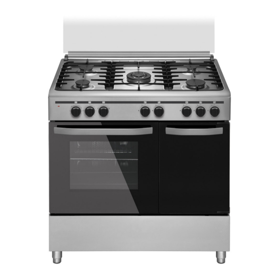
Summary of Contents for Orima OR 952 PBX
- Page 2 FOGÃO PORTA BOTIJA ORIMA 90x60 MANUAL DE INSTRUÇÕES Estimado Cliente, O nosso obejtivo é fazer com que obtenha os melhores resultados com o nosso aparelho. Este é produzido em modernas instalações, num ambiente de trabalho cuidadoso e tendo sempre presente o conceito de qualidade máxima.
- Page 3 Descrição do painel de comando Parte 8 Descrição das secções do forno Parte 9 Utilização do grupo de queimadores Parte 10 Modo de utilização do fogão Orima Parte 11 Utilização de protecção dos botões Parte 12 Manutenção e Limpeza Parte 13 Reciclagem...
- Page 4 1. O seu forno Orima está ajustado para uma Voltagem de 230 Volt, 50 Hz. para 1 fase 230V/400V, 50 Hz para 3 fases. 2. Se a corrente eléctrica do fusível em sua casa for inferior a 16 Amperes ( para 1 fase) 32 Amperes (para 3 fases) , contacte um Técnico qualificado para a instalação de fusível de 16/32 Amperes.
- Page 5 7. Certifique-se de que o fogão está instalado correctamente para os requisitos locais (por exemplo, os injectores devem ser adequados para o tipo de gás local e pressão do gás). 8. Ligue o seu Fogão Orima para gás LPG numa distância o mais curta possível e sem qualquer vazamento. Minímo de 40 cm – Máx 125 cm.
- Page 6 19. Coloque o tabuleiro por baixo da grelha e adicione 200 ml de água quqndo estiver a fazer frango assado. 20. Certifique-se de que o espeto se encontra bem fixado nos respectivos sectores quando o grelhador estiver a ser utilizado. 21.
- Page 7 INSTALAÇÃO DO SEU FORNO Ligação Eléctrica e Segurança 1. O seu forno é ajustado em conformidade com 230 Volt 16 Amperes (para 3 fases 230V/400V 32 Amperes) Se a corrente eléctrica for diferente destes valores, contacte um Técnico qualificado. 2. A ligação eléctrica do aparelho deverá ser feita somente em tomadas com ligação à terra em conformidade com os regulamentos em vigor.
- Page 8 7. O diâmetro interior do tubo flexível, para o bocal da mangueira de gás butano deverá deve ser de 6mm para os tubos do tipo de gás de casa. O diâmetro interior do tubo flexível, para o bocal da mangueira para gás natural, deverá ser de 15mm.
- Page 9 INSTALAÇÃO DOS PÉS DO FOGÃO Para instalar os pés do Fogão Orima, siga as instruções: 1. O suporte de fixação do pé é instalado no forno a partir do fundo do forno, indicado na Figura 1. As porcas são centradas sobre estes suportes, afim de aparafusar os pés (Figura 2).
- Page 10 Antes da primeira utilização, leia com atençao o manual de instruções. Neste Manual, encontram-se informações importantes para a sua segurança, como utilizar e como fazer a manutenção do seu fogão Orima. A conversão para o gás natural será feita através da troca do material auxiliar (injectores) entregue na recepção do fogão com um kit equivalente ao que foi instalado no fogão e...
- Page 11 Especificações Fogão 90x60 Natural Largura G 20-20 G 30-30 900 mm Embalagem Profundidade Injector mm 610 mm 1.30 0.96 Queimador Embalagem Altura Potência KW 925 mm 3.35 3.60 Embalagem Largura Injector mm 460 mm 1.15 0.85 Queimador Produto Rápido Profundidade Potência KW 400 mm 2.77...
- Page 12 Ajustamento de redução da chama: Para ajustar o seu forno para o tipo de gás que possuí, faça o ajustamento para reduzir a chama cuidadosamente, rodando com uma pequena chave de fendas, como apresentado abaixo no parafuso que se encontra no meio das torneiras de gás, bem como alterações do bico (Figura 5 e 6).
- Page 13 1. Utilize uma chave com cabeça especial para retirar e instalar os bicos – ver figura-7 2. Remova os bicos (Figura – 8) do queimador utilizando a chave especial e instale os novos bicos (Figura – 9). Figura - Figura - 8 Figura - 9 Alteração dos bicos: 1.
- Page 14 Figura - 11 Figura - 12 Figura - 10 FIGURA - 13 Figura - 14 Figura - 15...
- Page 15 DESCRIÇÃO DO PAINEL DE COMANDO...
- Page 16 DESCRIPTION OF THE OVEN SECTION Front right Rear right Wok burner Front electric Rear electric Rear left Front left burner (small burner or hotplate hot plate hot plate burner burner (big burner) (middle (middle burner) burner) burner) Grill burner Oven burner Timer Thermostat Turnspit...
- Page 17 DESCRIÇÃO DAS SECÇÕES DO FORNO QUEIMADOR QUEIMADOR QUEIMADOR DISCO ELÉCTRICO DISCO ELÉCTRICO QUEIMADOR QUEIMADOR DIREITO FRONTAL DIREITO DE TRÁS WOK OU FRONTAL DE TRÁS ESQUERDO DE TRÁS ESQUERDO FRONTAL (PEQUENO) (MÉDIO) DISCO ELÉCTRICO (MÉDIO) (PEQUENO) QUEIMADOR QUEIMADOR RELÓGIO TERMOSTATO ESPETO LÂMPADA ISQUEIRO GRELHADOR...
- Page 18 (OPCIONAL) 4. Se o seu forno Orima tem sistema de ignição do interruptor de botão de pressão, prima e vire a posição da válvula de gás e ao mesmo tempo pressione o botão de ignição.
- Page 19 4. Tempos de cozedura: Os resultados podem mudar de acordo com a corrente local, material com diferente qualidade, quantidade e temperatura. 5. Durante o tempo de cozedura, a porta do seu forno Orima não deve ser aberta com frequência. Caso contrário a circulação do calor pode ser desequilibrado e os resultados podem ser alterados.
- Page 20 GUIA CULINÁRIA Poisção da Tempo de Refeições Grelha Cozedura(min.) Bolo cremoso 30 - 35 Pastelaria 35 - 45 Biscoitos 20 - 25 Bolachas 20 - 35 Bolo 25 - 35 Pastelaria 30 - 40 Trançada Pastelaria fina 35 - 45 Pastelaria com 20 - 30 sabores...
- Page 21 5. Ao utilizar o Grelhador é importante manter a tampa aberta na distância especificada. Obterá melhores resultados utilizando o painel de Segurança e ao mesmo tempo protegerá o painel de controlo e os botões do seu fogão Orima Figura 1...
- Page 22 MANUTENÇÃO E LIMPEZA 1. Desligue a ficha de fornecimento de electricidade para o forno da tomada e corte o gás fechando a válvula de gás. 2. Nunca limpe a parte interior, painel, tampa, tabuleiros e todas as outras partes do forno utilizando escovas duras, palha- de-aço ou facas.
- Page 23 RECICLAGEM Eliminação correcta deste produto Esta marca indica que este produto não deve ser descartado junto com outros resíduos domésticos em toda a CE. Para evitar possíveis danos ao meio ambiente ou à saúde humana causados pela eliminação incontrolada de resíduos, recicle-o responsavelmente para promover a reutilização sustentável dos recursos materiais.
- Page 24 90x60 FREE STANDING GAS-ELECTRIC COOKER ORIMA WITH BOTTLE COMPARTMENT USER MANUAL Dear User, It is our ultimate desire that you achieve the best performance from our product, which has been passed through meticulous quality control checks and is manufactured in modern facilities.
-
Page 25: Table Of Contents
TABLE OF CONTENTS Part 1 Index Part 2 Important warnings Part 3 Installation of your oven Part 4 Installation of the oven feet Part 5 Technical features of your oven Part 6 Nozzle change operation Part 7 Descriptions of the control panel Part 8 Descriptions of the oven section Part 9 Using the burner groups Part 10... -
Page 26: Part 2 Important Warnings
IMPORTANT WARNINGS The cooker is supplied setup according to the conditions shown on the rating label which is stuck to the rear of the appliance. From this sticker you can learn for which gas type (LPG or NG) this appliance is configured when supplied. 1. -
Page 27: Part 3 Installation Of Your Oven
19. Please place the tray to the lowest shelf and add 200 ml water when you cook something in chicken roast section. 20. Make sure that rear pulley section of the grill swelling is fixed on V-bed on the grill when you use the grill swelling. 21. - Page 28 Gas Connection and Security 1. Before your appliance is connected to the gas supply, ensure that the gas category and pressure specifications shown in the data plate corresponds with your gas supply. If necessary call authorized service for adjusting to gas category. 2.
-
Page 29: Part 4 Installation Of The Oven Feet
INSTALLATION OF THE OVEN FEET In order to install the oven feet; 1. Foot attachment lath is installed on the oven from the bottom of the oven as shown in Figure 1. Nuts are centered on these lathes in order to screw feet (Figure 2). Complete the feet installation process by screwing the feet to the nuts (Figure 3). -
Page 30: Part 5 Technical Features Of Your Oven
Figure 1Figure 2 Figure 3 Figure 4 TECHNICAL FEATURES OF YOUR OVEN Before making the connections of your appliance: Before starting to use the appliance, read the user manual of the appliance carefully. In this user Manual, there are important information regarding your, our customers' security, how you will use it and how you will make its maintenance. - Page 31 Natural Specifications 90x60 Cooker Outer width 900 mm G 20-20 G 30-30 Outer depth 610 mm Injector mm 1.30 0.96 Outer height 925 mm Burner Power 3.35 3.60 Inner width 460 mm Injector mm 1.15 0.85 Rapid Burner Inner depth 400 mm Power 2.77...
- Page 32 Reduced Flame Gas Cock Adjustment: to adjust your oven acc. to the gas type, make the adjustment for reduced flame carefully by turning with a small screwdriver as shown below on the screw in the middle of the gas cocks as well as nozzle changes (figure 5 and 6). From From LPG to Natural...
- Page 33 Oven Burner Nozzle Change: 1. Remove the oven broiler cover that is fixed with two screws to the cavity. (figure 10) 2. Unscrew the screw that fixes the broiler to the cavity. Thus, the broiler is free from the cavity. (figure 11 3.
- Page 34 DESCRIPTION OF THE CONTROL PANELS...
-
Page 35: Part 9 Using The Burner Groups
DESCRIPTION OF THE OVEN SECTION Front right Rear right Wok burner Front electric Rear electric Rear left Front left burner (small burner or hotplate hot plate hot plate burner burner (big burner) (middle (middle burner) burner) burner) Grill burner Oven burner Timer Thermostat Turnspit... - Page 36 Using Gas Cooker: 1. Our gas ovens top and bottom burner working system is one by one. When you want use your preference burner, before you must make press the tap knob and wait nearly 5-10 second. Then you can to inflame trough with automatic ignition system (optional) or match.
-
Page 37: Part 10 Using Oven Section
LEVEL LEVEL LEVEL LEVEL LEVEL LEVEL 1000 145 mm 95 W 155 W 250 W 400 W 650 W 1500 180 mm 115 W 175 W 250 W 600 W 850 W 145 mm 1500 Rapid 135 W 165 W 250 W 500 W 750 W 180 mm 1150 2000... - Page 38 1. When your oven is operated first time, an odor will be spread out which will be sourced from using the heating elements. In order to get rid of this, operate it for 45 minutes while it is empty. In order to make cooking in your oven; oven switch must have been rotated and ignition must have been made.
- Page 39 COOKING TABLE Rack Cooking time Meals position (min.) Creamed cake 30 - 35 Pastry 35 - 45 Biscuit 20 - 25 Cooky 20 - 35 Cake 25 - 35 Braided cooky 30 - 40 Filo pastry 35 - 45 Savory pastry 20 - 30 Lamb meat 20 - 25...
-
Page 40: Part 11 Using The Knob Protection Sheet
USING THE KNOB PROTECTION SHEET 1. A safety panel is designed to protect control panel and the buttons when the oven is in Grill mode (Figure 1) 2. Please use this safety panel in order to avoid the heat to damage control panel and the buttons when the oven is Grill mode. -
Page 41: Part 12 Maintenance And Cleaning
MAINTENANCE and CLEANING 1. Disconnect the plug supplying electricity for the oven from the socket and cutoff the gas by closing the gas valve. 2. Never clean the interior part, panel, lid, trays and all other parts of the oven by the tools like hard brush, cleaning mesh or knife. -
Page 42: Part 13 Disposal Of Packaging
DISPOSAL OF PACKAGING The packaging materials protect the appliance during transport. By recycling the packaging it is possible to save raw materials and reduce waste volumes. If you dispose of the packaging yourself, ask local authorities for the location of the nearest collection centre. DISPOSAL OF ELECTRICAL AND ELECTRONIC APPLIANCES This appliance is marked in compliance with European Directive 2002/96/EC, Waste Electrical and Electronic Equipment (WEEE).
Need help?
Do you have a question about the OR 952 PBX and is the answer not in the manual?
Questions and answers