Table of Contents
Advertisement
Quick Links
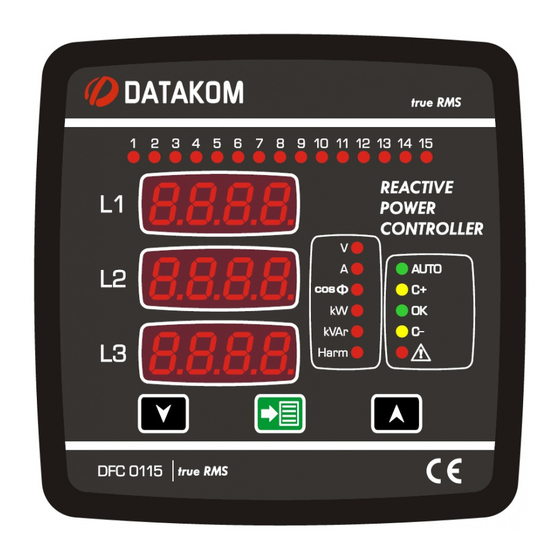
DFC-0115
REACTIVE POWER CONTROLLER
The DFC-0115 is an advanced, precision
15 step power factor control and metering
device, which continuously matches the
target cosø value of the load.
Installation and configuration of the DFC-
0115 is very simple thanks to the auto-
learning function.
Each step output supports single-phase,
two-phase, and three-phase connection of
capacitors and reactors.
SAFETY NOTICE
Failure to follow below
instructions will result in
death or serious injury
Electrical equipment should be installed only
by qualified specialist. No responsibility is
assured by the manufacturer or any of its
subsidiaries for any consequences resulting
from the non-compliance to these
instructions.
Check the unit for cracks and damages due
to transportation. Do not install damaged
equipment.
Do not open the unit. There is no
serviceable parts inside.
Fuses of fast type with a maximum rating of
6A must be connected to the power supply
and phase voltage inputs, in close proximity
of the unit.
Disconnect all power before working on
equipment.
When the unit is connected to the network
do not touch terminals.
Short circuit terminals of unused current
transformers.
Any electrical parameter applied to the
device must be in the range specified in the
user manual.
Do not try to clean the device with solvent or
the like. Only clean with a dump cloth.
Do not allow water to come in the unit.
Verify correct terminal connections before
applying power.
Only for front panel mounting.
INSTALLATION
Before Installation:
Read the user manual carefully,
determine the correct connection
diagram.
Remove all connectors and mounting
brackets from the unit, then pass the
unit through the mounting opening.
Put mounting brackets and tighten. Do
not tighten too much, this can break
the enclosure.
Make electrical connections with plugs
removed from sockets, then place
plugs to their sockets.
Make sure to use adequate fuses.
Do not subject the unit to water spill.
Below conditions may damage the
device:
Incorrect connections.
Incorrect power supply voltage.
Voltage at measuring terminals
beyond specified range.
Current at measuring terminals
beyond specified range.
Overloaded or short circuited relay
output terminals.
Below conditions may cause abnormal
operation:
Power supply voltage below minimum
acceptable level.
Power supply frequency out of
specified limits
Phase order of voltage inputs not
correct. (Without auto-correct function)
Current transformers not matching
related phases. (Without auto-correct
function)
Incorrect current transformer polarity.
(Without auto-correct function)
Inappropriate delay for switch on,
switch off delays of steps.
Current transformers must
be used for current
measurements. No direct
connection allowed.
Advertisement
Table of Contents

Subscribe to Our Youtube Channel
Related Manuals for Datacom DFC-0115

Summary of Contents for Datacom DFC-0115
- Page 1 INSTALLATION DFC-0115 REACTIVE POWER CONTROLLER Before Installation: Read the user manual carefully, The DFC-0115 is an advanced, precision determine the correct connection 15 step power factor control and metering diagram. device, which continuously matches the Remove all connectors and mounting target cosø...
-
Page 2: Electrical Connections
ELECTRICAL CONNECTIONS BUTTON FUNCTIONS Do not place the unit close to high electromagnetic noise emitting devices like contactors, high current busbars, switch mode power supplies. Although the unit is protected against electromagnetic disturbances, excessive disturbance can affect the operation, measurement precision and data communication quality. -
Page 3: Auto Setup
BUTTON FUNCTION 2. AUTO SETUP Hold pressed MENU button for 3 seconds to activate auto setup. Three phase voltage LErn should be seen at top inputs must be screen. connected for successful Push up arrow buttons 4 times to auto setup. navigate ctrF parameter. - Page 4 ENABLE AND DISABLE BUTTON FUNCTION PROGRAMMING MODE Choose required parameter by The DFC-0115 offers a set of adjustable using up and down arrows while parameters in order to provide the user parameter can be seen at top with maximum flexibility.
- Page 5 PARAMETER LIST DEFINITION STD MAX “CtrF” 500A 5000A DEFINITION STD MAX Current “ ” User 9999 Transformer Enter Password Primary value of The user password current should be entered. transformers. User password is set through “PASS” parameter. between 5/5A and “...
- Page 6 DEFINITION STD MAX “t-dU” 1 sec 1 sec 2000 Step switching delay When the unit decides to switch the step configuration, it continues measurements during this delay and sets the new step configuration calculated at the end of this delay. “t-CL”...
-
Page 7: Technical Specifications
TECHNICAL SPECIFICATIONS Supply Voltage: 85 - 300VAC (L1-N) 50 - 60Hz nominal (± %10) (L1-N) Generator Input: 70 - 300 V AC (P-N) Measurement Inputs: Voltage: 10 - 300 V AC (Ph-N) 20 - 520 V AC (Ph-Ph) Current: 0.05 - 5.50 A AC Frequency: 30 - 100 Hz Accuracy: Voltage:... -
Page 8: Connection Diagram
CONNECTION DIAGRAM Tel: +90-216-466 84 60 Fax: +90-216-364 65 65 e-mail: datakom@datakom.com.tr http: www.datakom.com.tr...
Need help?
Do you have a question about the DFC-0115 and is the answer not in the manual?
Questions and answers