Advertisement
Quick Links
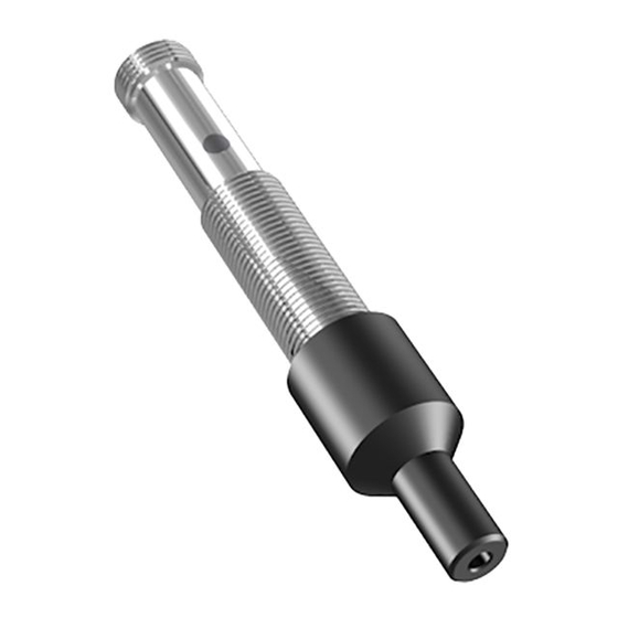
INSTALLATION GUIDE
Ultrasonic Sensor Series UFA2, UFA-CP and UFA-6000
For further information please see the data sheet at www.waycon.biz/products/ultrasonic-sensors/
FIRST STEPS
WayCon Positionsmesstechnik GmbH would like to thank you for the trust you have placed in us and
our products. This manual will make you familiar with the installation and operation of our ultrasonic
sensors. Please read this manual carefully before initial operation!
Unpacking and checking:
Carefully lift the device out of the box by grabbing the housing. After unpacking the device, check
it for any visible damage as a result of rough handling during the shipment. Check the delivery for
completeness. If necessary consult the transportation company, or contact WayCon directly.
SAFETY NOTICES
• These products are neither allowed to be used as safety- or emergency shut-off devices, nor in other
applications, where a malfunction of this product may result in personal injury.
• Failure to follow this notice may result in serious or fatal injury.
MOUNTING NOTICES
• The sensor can be mounted with the two M12 nuts (UFA2/UFA-CP) or M30 nuts (UFA-6000) which
are included in the delivery.
• The sensor has to be protected against mechanical loads for example shocks and impacts.
• The sensor can be mounted in any position, however a vibration-free or vibration-dampening
assembly must be observed.
• The transducer surface as well as the field of the detection beam must be kept free mandatorily. You
need to pay attention on having no disturbing objects between the sensor and the target object
within the detection beam. Otherwise the sensor will detect the disturbing object instead of the
target object required.
• The object reflects a part of the ultrasonic in the
diffuse mode - this reflected sound will be evaluated
by the sensor. Objects with a smooth surface are
reliably detected up to a tilting angle of approx. 10°.
The max. allowed tilting angle increases on objects
with a rough or heavy structured (granular) surface.
Advertisement

Related Manuals for Waycon UFA-CP Series


Summary of Contents for Waycon UFA-CP Series
- Page 1 For further information please see the data sheet at www.waycon.biz/products/ultrasonic-sensors/ FIRST STEPS WayCon Positionsmesstechnik GmbH would like to thank you for the trust you have placed in us and our products. This manual will make you familiar with the installation and operation of our ultrasonic sensors.
-
Page 2: Electrical Connection
ELECTRICAL CONNECTION UFA2 and UFA-6000 UFA-150-CP Connection cable Analog output Switching output Analog output Switching output Analog output Teach Teach Teach Teach Switching output Analog output Switching output connector M12 circuit diagram UFA2/UFA-6000 circuit diagram UFA2/UFA-6000 (male) analog output switching output Pin 1 Pin 1 Pin 4... - Page 3 TEACHING FUNCTION UFA2 AND UFA-6000 SWITCHING OUTPUT Teaching the window size: The window size is defined by two switching limits. Procedure: 1. Place the target on the position of near switching point. 2. Connect the teaching line (Pin 2) with +V (Pin 1) for 0.1...2 s. LED flashes slowly (1 Hz). 3.
- Page 4 TEACHING FUNCTION UFA-150-CP ANALOG OUTPUT Teaching the measurement range: The two measuring limits are set by connecting the teaching line with either the power supply GND (0 V) or +V (+24 VDC). The voltage must be active for min. 1 s on the teaching line. During the teaching procedure the LED shows if the sensor has detected the object.
- Page 5 TEACHING FUNCTION UFA-150-CP SWITCHING OUTPUT Retroflective mode: In window operation the sensor detects only targets which are within the window limits. The same function can also be used to simulate a kind of retro-reflective sensor. The reflector is mounted in the small window between Teach A and Teach B (see drawing below).
- Page 6 DETECTION BEAMS UFA2-200-A: Standard version with analog output blind range target: plate 100 x 100 mm target: round bar Ø 10 mm UFA2-200-PN: Standard version with switching output blind range target: plate 100 x 100 mm target: round bar Ø 10 mm UFA2-FB-150: Focus beam version target: plate 20 x 20 mm target: round bar Ø...
- Page 7 INFLUENCES ON THE MEASUREMENT Environmental influences: Ultrasonic sensors are made for the use in atmospheric air. Environmental Influences like rain, snow, dust or smoke have no influence on the accuracy of the measurement. However, measurements under pressure (higher that the atmospheric pressure) are not possible with ultrasound sensors. Strong wind or air turbulences may lead to instability in measurement values.
-
Page 8: Declaration Of Conformity
DECLARATION OF CONFORMITY Based on: EN 60947-5-2 + amendments (proximity switches) EN 60947-5-7 + amendments (proximity sensors with analogue output) This is to certify that the following products correspond to the mentioned specifications. Classification Ultrasonic Sensors Series UFA-150-CP, UFA2, UFA-6000 Test on immunity IEC 61000-6-2 (Industry) Type of test...