Table of Contents
Advertisement
Quick Links
ENGLISH
WEIGHT TRANSMITER
T200F
with RS232 serial, analog 4-20 mA 0-10V
Fieldbus OPTION : MODBUS TCP, PROFINET, PROFIBUS, ETHERNET IP, CAN OPEN, ETHERCAT
Installation and User Manual
Pesage, Dosage, Machine de Conditionnement
ADN Pesage: 7 Rue du bois Malhais, 78990 Saint Germain de la Grange France
Tél.: 33(0) 1 48 63 00 76 - Télécopie: 33(0) 1 48 63 72 06 - Mail:
contact@adnpesage.fr
Advertisement
Table of Contents

Related Manuals for ADN pesage T200F Series

Summary of Contents for ADN pesage T200F Series
- Page 1 Installation and User Manual Pesage, Dosage, Machine de Conditionnement ADN Pesage: 7 Rue du bois Malhais, 78990 Saint Germain de la Grange France Tél.: 33(0) 1 48 63 00 76 - Télécopie: 33(0) 1 48 63 72 06 - Mail:...
-
Page 2: Table Of Contents
Pesage TABLE OF CONTENTS PRECAUTIONS ...................…...Page INTRODUCTION ..................…….Page TECHNICAL FEATURES .................. Page INSTALLATION ...................….. Page FRONT PANEL OF THE INSTRUMENT ............….. Page USING THE KEYBOARD ................. Page INFO DISPLAY ....................… Page OPERATING FUNCTIONS ................Page SETTING ....................…. Page DIAGRAM OF THE MENU ................Page CONFIGURATION PARAMETERS .............. -
Page 3: Precautions
Any attempt to dismantle or modify the instrument which is not expressly authorised will invalidate the warranty and will relieve ADN Pesage from all liability. Installation and maintenance of this instrument must be entrustedto qualified personnel only. -
Page 4: Introduction
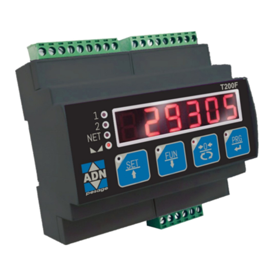
Pesage INTRODUCTION The T200F is a weight transmitter to be combined with the load cells to detect the weight in every situation. The module is easy to install and must be mounted on a 35 mm DIN rail or OMEGA bar. The weight, the status of the instrument, the setting parameters and any errors are all clearly shown on the display. - Page 5 Always cite this data when requesting information or instructions concerning the instrument, as well as the program number and version that are shown on the cover of the manual and on the display when the instrument is switched on. ADN PESAGE WARNINGS The following procedures must be entrusted to qualified personnel.
-
Page 6: Technical Features
Pesage TECHNICAL FEATURES Power supply 12 ÷ 24 Vdc ± 15 % Max. absorption Isolation Class II Installation category Cat. II Operating temperature -10°C ÷ +50°C (max humidity 85% without condensate) Storage temperature -20°C ÷ +70°C Weight display 6 digit 7-segment red LEDs (h 14 mm) 4 3mm indicator LEDs Keyboard 4 capacitive keys... -
Page 7: Installation
Transmetteur de pesage T200F : Manuel d’utilisation et d’installation INSTALLATION GENERAL DATA The T200F comprises a motherboard, to which various options can be added; the motherboard is housed in a plastic 35mm DIN rail mount enclosure. The T200F should not be immersed in water, subjected to jets of water, and cleaned orwashed with solvents. - Page 8 Pesage The instrument is powered via terminals 22 and 23. The power cord must be channelled separately from the other cables. The instrument is in insulation class II (double insulation) and there is no ground terminal provided, which is however necessary to Make sure you have a valid ground connection.
- Page 9 Transmetteur de pesage T200F : Manuel d’utilisation et d’installation LOGIC INPUTS The two logic inputs are opto-isolated. The cable connected to the logic input should not be chan- nelled withthe power cables. INPUT 1 Minimise the length of the connecting cables. INPUT 2 COM.
- Page 10 Pesage The transmitter provides an analogue output in current or voltage. mA+ (300 Ω max) Analogue output in voltage: range from 0 to 10 Volt or from 0 to 5 V+ (10 kΩ min) Ana- Analogue output in current: range from 0 to 20 mA or from 4 to 20 SHIELD Analog transmission can be sensitive to electromagnetic interference, it is therefore recommended that the cables...
- Page 11 Transmetteur de pesage T200F : Manuel d’utilisation et d’installation To connect to the MASTER, use a standard twisted pair Ethernet DESCRIPTION cable with RJ45 connector. The RJ45 Ethernet connection cable has a variable maximum length, depending on the type of cable. A common Cat5 shielded cable can have a maximum length of about 180 m.
- Page 12 Pesage PROFINET CONNECTION The Profinet connector is RJ45, the same as the Ethernet interface. There are two RJ45 connectors to allow connection of multiple in- struments in the same network. Refer to the previous page for connection notes and warnings. Features: PROFINET IO Real Time (RT) communications Modbus-TCP server...
- Page 13 Transmetteur de pesage T200F : Manuel d’utilisation et d’installation PROFIBUS DP CONNECTION Signal Description B line +RxD/+TxD, level RS485 Request to send Ground (isolated) + 5V Bus Output +5V termination (isolated) A line -RxD/-TxD, level RS485 Housing Cable shield Internally connected to protective earth according to Profibus specification For connection to the Profibus Master, use a standard Profibus cable.
- Page 14 Pesage Signal Description CAN_L CAN low bus line CAN_GND CAN_H CAN high bus line CANopen is an higher-layer communication protocols based on a CAN seria bus system. For the connection using a cable with a twisted pair differential and common return in accordance with ISO 11898. The length of the bus is limited by the speed of communication chosen according to Bit Rate Max.
-
Page 15: Front Panel Of The Instrument
Transmetteur de pesage T200F : Manuel d’utilisation et d’installation FRONT PANEL OF THE INSTRUMENT The T200F has a 6-digit lit display, 4 status LEDs and four keys with corresponding LEDs for con- firming pressing of the key. In operating mode, the display shows the weight and the LEDs indicate the status of weight and theset- points. -
Page 16: Using The Keyboard
Pesage USING THE KEYPAD The instrument is programmed and controlled via the capacitive keypad consisting of 4 keys, all with dual function. The selection of one of the two key functions is automatically established by the instru- ment based on operation in progress. In general, the programming menus are managed using keys and ... - Page 17 Transmetteur de pesage T200F : Manuel d’utilisation et d’installation FUNCTION DURING THE PROGRAMMING MENU NAVIGATION It selects the next menu. It selects the previous menu. It exits the programming menu or returns to the upper level. It accesses the relative sub-menu or programming or confirms the selected parameter.
- Page 18 Pesage KEYBOARD LOCKING/UNLOCKING FUNCTIONS OPERATION DESCRIPTION Keyboard Lock - The keys are disabled until released. The display goes into low power mode. The instrument is locked by simultaneously pressing the ZERO + PRG keys for 5 seconds. By switching the instrument on and off the instrument automatically unlocks.
-
Page 19: Info Display
Transmetteur de pesage T200F : Manuel d’utilisation et d’installation INFO DISPLAY PdAt01 When the instrument is switched ON, a display test is run followed by the identifica- tion code and then the version of the software, in that order. These codes are to be cited when requesting assistance When is not in progress a programming procedure, the display shows the weight measured in kilograms. -
Page 20: Operating Functions
Pesage OPERATING FUNCTIONS Once calibrated, the display shows the current weight whenever it is switched on. The following are the possible operations that can be carried out from the keyboard when viewing the weight of the instrument. OPERATION FUNCTION Display of Gross Weight to Net Weight. Display of the peak. - Page 21 Transmetteur de pesage T200F : Manuel d’utilisation et d’installation When the instrument is in the “Net” operating mode (“NET” LED on) the 0 key performs the auto-tare function. When the instrument is in the “Gross” operating mode (“NET” LED off) the 0 key performs the gross weight resetting function.
- Page 22 Pesage PEAK FUNCTION The instrument continuously memorises the peak value of the gross weight. This function is available only if the peak calculation function is enabled via the corresponding parameter in the set-up menu of the instrument. The peak display is shown by the letter P on the left of the display. The peak value is detectedat the same frequency of acquisition of the weight (see table on filters).
- Page 23 Transmetteur de pesage T200F : Manuel d’utilisation et d’installation PROGRAMMING THE WEIGHT SET-POINTS The set-points are compared with the weight to drive the relative logic output. The comparison criterionis defined during set-up of the logic inputs/outputs (see the relevant section). To access the Set points setting, press the SET key while viewing the weight MENU MESSAGE...
-
Page 24: Setting
Pesage SETTING GENERAL DATA All functions of the T200F are activated and modified by accessing a simple setup menu, shown on the next page. All settings that are selected or activated remain in the memory even after the transmitter has been switched off. The T200F is preconfigured with a default setting. - Page 25 Transmetteur de pesage T200F : Manuel d’utilisation et d’installation CHANGING AND ENTERING THE PARAMETERS: The procedure for accessing the menu depends on the operating mode selected: FREE or METRIC. MENU ACCESS IN FREE OPERATION MODE. In the event of FREE operation all instrument parameters can be changed by the operator. MENU ACCESS IN METRIC OPERATION MODE.
- Page 26 Pesage To access the setup menu, press the PRG key and then the SET key and hold them down simultaneously for 3 seconds or press and hold the PRG key for at least 6 seconds . Access by confirming your choice with the PRG key. MESSAGE NAME DESCRIPTION...
- Page 27 Transmetteur de pesage T200F : Manuel d’utilisation et d’installation TEST MENU MENU MESSAGE NAME DESCRIPTION TYPE Display of the signal in mV/V in input to the S1GnAL Cell signal Vis. instrument Display of the weight with a resolution 10 H1 rES. Resolution x10 Vis.
-
Page 28: Diagram Of The Menu
Pesage DIAGRAM OF THE MENU Page 27... -
Page 29: Configuration Parameters
Transmetteur de pesage T200F : Manuel d’utilisation et d’installation CONFIGURATION PARAMETERS All the parameters that can be set are described in the following pages. At the end of each parameter description, where present, the fieldbus address corresponding to the parameter is shown. If the pa- rameter is the selectable type, the value to be entered in the register for the desired selection is shown between “[ ]”. -
Page 30: Calibration
Pesage SySt.FS CAPACITY OF THE WEIGHING SYSTEM [1301-1302] Programming the useful capacity (net) of the weighing system. Values: from 0 to Load Cell Capacity Default: 0 dEAd L. FIXED TARE OF WEIGHING SYSTEM [1106-1107] Programming the fixed tare value of the weighing system Values: from 0 to Capacity Value Default: 00000 CAL.tyP... - Page 31 Transmetteur de pesage T200F : Manuel d’utilisation et d’installation CONFIGURATION/CALIBRATION EXAMPLE Set the parameters listed above to perform theoretical calibration of the Full Scale of the T200F. This procedure must be completed with calibration of the zero-point as described later on. The procedure ensures good precision of the system (maximum error <1% FS) when there are no mechanical problems.
- Page 32 Pesage CALIBRATION OF SAMPLE WEIGHTS The calibration procedure described below should be carried out using sample weights and/or a sample product pre-weighed on a weighing system. Before proceeding with calibration of the full scale, always perform zero calibration. During the calibration phase, the weight is shown on the display in alternation with the text CAL. WARNING: Switching off the instrument without exiting the set-up menu cancels any changes made during the programming process.
- Page 33 Transmetteur de pesage T200F : Manuel d’utilisation et d’installation TABLE CALIBRATION It allows you to manually program up to five calibration points, in addition to zero. The values corre- sponding to those resulting from the linearisation procedure with sample weights. This way you can view the values automatically determined with this procedure or modify and program them in accordance with predetermined values.
- Page 34 Pesage ANALOG - ANALOG OUTPUT PARAMETERS (OPTIONAL) rAnGE.. ANALOG OUTPUT RANGE [1506] Select the analogue output range. Selectable setting: 0÷10 Vdc [0] 0÷5 Vdc [1] 4÷20 mA [2] 0÷20 mA [3] Default: 0÷10 Vdc NodE.. ANALOG OUTPUT OPERATION MODE [1505] Selection of the value to be associated to the analogue output, corresponding to the net weight, gross weight or peak value.
- Page 35 Transmetteur de pesage T200F : Manuel d’utilisation et d’installation FS.AdJ.. FULL SCALE OFFSET REGULATION Measure the analogue output value with a multimeter to perform the full scale (FS) calibration. Use the keys to regulate the analogue output. Hold the key for a quick change. Press key to go back to the ANALOG menu.
-
Page 36: Serial Parameters
Pesage SERIAL COMMUNICATIONS PARAMETERS This menu makes it possible to configure the COM1 and COM2 serial ports and the communication parame ters. The instrument has two independent serial ports: COM1 always with interface RS232 ; COM2 can be fitted with either of the following interfaces: RS485, ETHERCAT, ETHERNET, ETHERNET IP, PROFINET. - Page 37 Transmetteur de pesage T200F : Manuel d’utilisation et d’installation C1baud. COM1 BAUD RATE Defines the baud rate of serial port RS232. The value must be set at the same value as PC/PLC or remote display. Values that can be selected: 1200 2400 4800...
- Page 38 Pesage COM 2 PARAMETERS WHEN PRESENT RS485 C2 Nod.. COM2 OUTPUT MODE Selecting the value transmitted on output RS 485. Values that can be selected: GroSS PEAk Default: nEt C2Prot... COM2 PROTOCOL It defines how to use the RS485 serial port: Values that can be selected: None: Serial communication OFF Contin: Continuous transmission of the weight string.
- Page 39 Transmetteur de pesage T200F : Manuel d’utilisation et d’installation C2ForN COM2 PROTOCOL Type of frame. For the SLAVE or MODBUS protocol you cannot select 7-bit data format (E-7-1 e O-7-1): Values that can be selected: n-8-1 n-8-2 E-7-2 E-8-1 o-7-2 o-8-1 Default: n-8-1 C2Addr.
- Page 40 Pesage COM 2 PARAMETERS WHEN PROFINET / ETHERCAT IS PRESENT En.FbuS. FIELDBUS ENABLING Enabling PROFINET / ETHERCAT fieldbus, if OFF error messages concerning FIELDBUS communication are never displayed: Values that can be selected: Default: OFF InP.rEG.. INPUT AREA DIMENSION Input area dimension for fieldbus (value expressed in Bytes). Values that can be selected: 32, 64, 96, 128 Default: 128...
- Page 41 Transmetteur de pesage T200F : Manuel d’utilisation et d’installation PARAMETERS COM 2 WHEN ETHERNET IP IS PRESENT En.FbuS. FIELDBUS ENABLING Enabling ETHERNET IP fieldbus, if OFF error messages concerning Fieldbus communication are never displayed: Values that can be selected: Default: OFF IP ADDRESS ETHERNET IP protocol address Values from 0.0.0.0 to 255.255.255.255...
- Page 42 Pesage COM 2 PARAMETERS WHEN ETHERNET IS PRESENT IP ADDRESS ETHERNET protocol IP address Values from 0.0.0.0 to 255.255.255.255 Default: 192.168.0.201 SubnEt SUBNET MASK ETHERNET protocol Subnet Mask. Values from 0.0.0.0 to 255.255.255.255 Default: 255.255.255.0 GatE GATEWAY ETHERNET protocol gateway. Values from 0.0.0.0 to 255.255.255.255 Default: 192.168.0.1 Port...
- Page 43 Transmetteur de pesage T200F : Manuel d’utilisation et d’installation COM 2 PARAMETERS WHEN PROFIBUS DP IS PRESENT En.FbuS. FIELDBUS ENABLING Enabling PROFIBUS DP fieldbus, if OFF error messages concerning Fieldbus communication are never displayed: Values that can be selected: Default: OFF Addr.Pr PROFIBUS ADDRESS Programming the address used in the PROFIBUS protocol.
- Page 44 Pesage COM 2 PARAMETERS WHEN CANOPEN IS PRESENT En.FbuS. FIELDBUS ENABLING Enabling CANOPEN fieldbus, if OFF error messages concerning Fieldbus communication are never displayed: Values that can be selected: Default: OFF Addr.Co CANOPEN ADDRESS Programming the address used in the CANOPEN protocol. Values: from 0 to 126 Default: 1 Baud.Co..
-
Page 45: Input/Output Parameters
Transmetteur de pesage T200F : Manuel d’utilisation et d’installation INPUT/OUTPUT PARAMETERS FUn.1n.1 INPUT 1 FUNCTION Selecting the function associated with input 1. [1401] Values that can be selected: Zero: It calibrates to zero. [0] Tare: It executes the automatic tare. [1] Del.Tar: It cancels the tare. - Page 46 Pesage Selecting the output status if normally open or closed: [1404] n. oPEn. Relay 1 is normally open. [0] n.CLoSE Relay 1 is normally closed. [1] Defaul: n. oPEn. Select if positive or negative values have to be compared. [1405] PoSIt..
- Page 47 Transmetteur de pesage T200F : Manuel d’utilisation et d’installation NodE 2 SET-POINT 2 OPERATING MODE Select in sequence 4 operating criteria of set-point 2: [1410] Comparison with net weight, with gross weight or with peak. In the latter case the comparison is carried out with the last acquired peak value, even when the peak function is not active.
- Page 48 Pesage dELAy2 SET-POINT 2 DELAY [1416] Value of time, in tenths of a second, after which, when the set weight value is exceeded, the output associated with set-point 2 is enabled. The function is not active with programmed time equal to zero Values: from 000 to 999 Default: 0 Page 47...
-
Page 49: Weighing Parameters
Transmetteur de pesage T200F : Manuel d’utilisation et d’installation WEIGHING PARAMETERS The parameters in this menu permit adjustment of the times for acquisition and updating of the display and manual or automatic resetting by the transmitter. INSTRUMENT OPERATION Selecting the operation of the instrument. In case of a change from FREE operation to METRIC operation, to confirm the setting authentication is required through the password of authorised personnel. - Page 50 Pesage 0-trAC ZERO TRACKING [1306] This function allows you to perform temporary zero calibration compensating for the temperature drift of the weight. Switching off the transmitter automatically restores the previous zero calibration. The maximum weight that can be reset by this parameter is 2% of the capacity of the system. To disable this function, set the value 0.
-
Page 51: Filter - Setting Filter Parameters
Transmetteur de pesage T200F : Manuel d’utilisation et d’installation FILTER - SETTING FILTER PARAMETERS d1G.bAn. WEIGHT FILTER VALUE [1201] This parameter adjusts not only the refresh rate of the display, but specially the serial and analogue output. The maximum refresh rate of the display is limited to 25 Hz High filter values speed up the weight update. - Page 52 Pesage Nonot. MONOTONY TIME [1204 Parameter used to stabilize the weight when continuous variation of the last digit is detected. Normally used in case of resolution of the weight exceeding 10,000 divisions or with low sensitivity of the input signal. Value expressed in mS. Values: from 0 to 999.
-
Page 53: Setting Functional Features
Transmetteur de pesage T200F : Manuel d’utilisation et d’installation SETTING FUNCTIONAL FEATURES Std. by. STAND BY [1001] Idle time beyond which the instrument automatically assumes a low brightness status and keypad lock. 0 = deactivated function. Values: from 0 to 999. Default: 0 LoCk. - Page 54 Pesage DISPLAYED PARAMETERS ONLY IF OPTIONAL MEMORY INSTALLED dAt.LoG. DATALOGGER [1005] Allows you to save the weight and I/O status in the optional memory in Excel format. The logging can be a single measurement or a continuous series of measurements from the start of storage (max 1000 measurements).
- Page 55 Transmetteur de pesage T200F : Manuel d’utilisation et d’installation LoGdnL. DOWNLOAD LOG Log download function, the records are transmitted through the USB key of the instrument. This function can be interrupted at any time by pressing the ZERO key. At the end of the transmission you are prompted to delete the log, confirm by pressing PRG or cancel by pressing the ZERO weight key.
-
Page 56: Set Date And Time
Pesage SET DATE AND TIME This menu is shown only with clock hardware installed. dAtE SET DATE Parameter for the adjustment of the current date Format of selectable value: dd.mm.yy dd from 01 to 31 mm from 01 to 12 yy from 00 to 99 Default: actual date t1NE... -
Page 57: Upload/Download Function
Transmetteur de pesage T200F : Manuel d’utilisation et d’installation UPLOAD/DOWNLOAD FUNCTION The TESTER 1008 must be connected to the serial COM1 (RS232) of the instrument. This feature allows you to download or upload the setup configuration and calibration data stored in the instrument. -
Page 58: Access Viewing
Pesage ACCESS VIEWING This menu only appears in case of METRIC functioning. SUB MENU MESSAGGE NAME DESCRIZIPTION TYPE Procedure for wiewing last access of ACC-01 Access 01 authorized personnel. Procedure for wiewing last but one access of ACC-02 Access 02 authorized personnel. -
Page 59: Alibi Memory
Transmetteur de pesage T200F : Manuel d’utilisation et d’installation ALIBI MEMORY CONSULTATION This menu only appears in case of METRIC functioning. SUB MENU MESSAGGE NAME DESCRIZIPTION TYPE RANGE Aliby Procedure for consulting weigh ALi.NEN SEE.NEN. memory 0÷959999 stored in aliby memory. consultation In case of METRIC functioning and with aliby memory enabled: •... -
Page 60: Serial Communication Protocols
Pesage SERIAL COMMUNICATION PROTOCOLS CONTINUOUS, AUTOMATIC AND MANUAL ASCII PROTOCOLS The continuous transmission is carried out at the refresh rate of the weight, consistent with the serial transmission baud rate. In case of communication on the ethernet port, the continuous transmission frequency is limited to 12.5 Hz. - Page 61 Transmetteur de pesage T200F : Manuel d’utilisation et d’installation SLAVE TRANSMISSION PROTOCOL LIST OF THE CONTROLS AVAILABLE: 1. Request for the net and gross weight and current peak. 2. Execution weghing command 3. Autotare command 4. Zero command 5. Peak reset command 6.
- Page 62 Pesage Master: <Addr> “P” EOT T200F: <Addr> “P” <status> <weight> <ID weight> ETX <chksum> EOT or <Addr> NAK EOT 3 AUTO-TARE COMMAND Master: <Addr> “A” EOT T200F: <Addr> “A” ACK EOT or <Addr> NAK EOT 4. SEMI-AUTOMATIC ZERO COMMAND Master: <Addr> “Z” EOT T200F: <Addr>...
- Page 63 Transmetteur de pesage T200F : Manuel d’utilisation et d’installation 12. CHANGE FROM NET TO GROSS WEIGHT Master: <Addr> “CL” EOT T200F: <Addr> “C” ACK EOT or <Addr> NAK EOT 13. DELETE TARE COMMAND MASTER: <Addr> “DT” EOT T200F: <Addr> “D” ACK EOT or <Addr> NAK EOT 14.
- Page 64 Pesage PRINTER PROTOCOL Data transmission protocol to Plus Printer Printing can be started by pressing a key (see section FUNCTION OPERATIONAL) or by input (see paragraph SETTING I/O). Here is an example of printer. 216/06/16 15:32 209.0 kg Gross 211.5 kg Tare 2.5 kg Peak...
- Page 65 Transmetteur de pesage T200F : Manuel d’utilisation et d’installation MODBUS RTU PROTOCOL The addresses set out in the tables follow the standard routing specified in the reference guide of Modicom PI-MBUS-300 an extract of which is provided below to help the user communicate with the instrument. “All data addresses in Modbus messages are referenced to zero.
- Page 66 Pesage LIST OF THE MODBUS PROTOCOL HOLDING REGISTERS The instrument parameters that can be read or programmed via the communication interfaces available on the instrument, depending on the hardware configuration, are listed in the following table. R type registers are readable while W type are writeable. In case of Modbus TCP protocol, the address of the instrument (the “Unit Identifier”...
- Page 67 Transmetteur de pesage T200F : Manuel d’utilisation et d’installation 1110 Gravity zone of use (MSB) (*) R/W INT. value - Most significant word 1111 Gravity zone of use (LSB) (*) R/W INT. value - Less significant word 1151 Cal. table Zero signal (MSB) (*) R/W INT.
- Page 68 Pesage 1410 Output mode 2—F unction R/W See correspondence on page 44 1411 Output mode 2— Logic R/W See correspondence on page 45 1412 Output mode 2— Polarity R/W See correspondence on page 45 1413 Output mode 2 — Stability R/W See correspondence on page 45 1414 Hysteresis output 2...
- Page 69 Transmetteur de pesage T200F : Manuel d’utilisation et d’installation TABLE D - DECIMALS AND DIVISION VALUE CODING ADDRESS DESCRIPTION ACCEPTED VALUES 1104 Division value 1 - 2 - 5 - 10 - 20 - 50 1105 Number of decimals 0 - 1 - 2 - 3 - 4 TABLE E - DATA REGISTER / COMMAND REGISTER CODING REGISTER COMMAND REGISTER FUNCTION...
- Page 70 Pesage INSTRUMENT RESPONSE TIMES The instrument, to satisfy most requests, uses a variable time in accordance with the programming of the instrument parameters and the type of request as per table: Update frequency of measurements 12,5 Hz 50 Hz 100 Hz 250 Hz 1000 Hz Analogue output update frequency...
- Page 71 Transmetteur de pesage T200F : Manuel d’utilisation et d’installation USE OF SERIAL APPLICATIONS VIA THE USB PORT PC software “OPTIMATION” allows: • total configuration of all the setup parameters; • testing of the different hardware sections; • consultation of the instrument documentation •...
-
Page 72: Fieldbus Protocol
Pesage FIELDBUS PROTOCOL The following table lists the registers of the input area (produced from the instrument and read by the master), common to all PROFIBUS, PROFINET, ETHERCAT, ETHERNET/IP fieldbuses. The registers are 16 bit in size. The input area is updated at a fixed frequency of 150 Hz (80 Hz in case of PROFIBUS). - Page 73 Transmetteur de pesage T200F : Manuel d’utilisation et d’installation Number of readings on 69-70 INT. value average 71-72 Monotony Time INT. value 73-74 Oscillations Time INT. value 75-76 Oscillations Range INT. value 77-78 Full Scale (MSB) INT. value - Most significant word 79-80 Full Scale (LSB) INT.
- Page 74 Pesage The following table lists the registers of the output area (written by the master and acquired by the instrument), common to all PROFIBUS, PROFINET, ETHERCAT, ETHERNET / IP Fieldbuses. The registers are 16 bit in size. The registers written by the master in the output area, are read by the instrument at a fixed frequency of 150 Hz.
- Page 75 Transmetteur de pesage T200F : Manuel d’utilisation et d’installation 77-78 Input 1 mode —Logic See correspondence on page 43 79-80 Input 1 mode —Polarity See correspondence on page 44 81-82 Input 1 mode —Stability See correspondence on page 44 83-84 Hysteresis input 1 INT.
- Page 76 Pesage Full Scale Calibration: Put a know weight on the system and write its value in the Data Register (from byte 3 to 6). Put value Hex 5 in Command Register. The weight value will be displayed. Page 75...
- Page 77 Transmetteur de pesage T200F : Manuel d’utilisation et d’installation CANOPEN - DESCRIPTION The protocol supports the CiA DS301 “communication profile area”. Network Management (NMT) manages Pre-Operational, Operational, Stopped, Reset and Reset Com- munication states with its protocols. The Heartbeat protocol is supported, setted by default at 1 second, and can be switched off by pro- gramming at 0 the intervention time.
- Page 78 Pesage SPECIFICATION NMT slave Error Log Heartbeat producer Boot-up Range ID nodo 1 - 127 CANopen bit-rates 10 – 1000 kbit/sec Numero di PDO 1 TPDO Modalità PDO Event-triggered (timer) Synchronous (cyclic) Synchronous (acyclic) Mappatura PDO Si (6 obj/PDO) Emergency message Si (Producer) Numero di SDO 1 SDO server (“expedited”...
- Page 79 Transmetteur de pesage T200F : Manuel d’utilisation et d’installation CANOPEN - OBJECT DICTIONARY - COMMUNICATION PROFILE AREA GENERIC PARAMETERS Index Sub-Index Name Description Type Attribute 1000h DEV_TYPE Device type information (*) 1001h ERR_REG Error log 1005h COB_ID SYNC COB_ID Sync message (80h) Sub-index number(4) Store all parameters (**) 1010h...
- Page 80 Pesage T_PDO COMMUNICATION PARAMETERS Index Sub-Index Name Description Type Attribute Sub-index number(5) COB_ID used from PDO (180h + Node_ID ) Transmission type PDO (*) 1800h AI_T_PDO_CPAR Inhibition time (0) Reserved Event timer (expressed in ms, default 8 ms) (*) PDO Transmission type: 00h = synchronous acyclic (PDO is transmitted following the receipt of SYNC, but only if a new me- asurement has been acquired).
- Page 81 Transmetteur de pesage T200F : Manuel d’utilisation et d’installation T_PDO COMMUNICATION PARAMETERS Index Sub-Index Name Description Type Attribute Sub-index number(5) COB_ID used from PDO (180h + Node_ID ) Transmission type PDO (*) 1801h AI_T_PDO_CPAR2 Inhibition time (0) Reserved Event timer (expressed in ms, default 8 ms) (*) PDO Transmission type: 00h = synchronous acyclic (PDO is transmitted following the receipt of SYNC, but only if a new me-...
- Page 82 Pesage PARAMETERS DEFINED BY THE MANUFACTURER Index Sub-Index Name Description Type Attribute Sub-index number(1) 2000h UD_STATUS Status Register Sub-index number(1) 2001h UD_LORDO Gross weight Sub-index number(1) 2002h UD_NETTO Net weight Sub-index number(1) 2003h UD_PICCO Peak Sub-index number(1) 2004h UD_IN Digital input Sub-index number(1) 2005h UD_OUT...
- Page 83 Transmetteur de pesage T200F : Manuel d’utilisation et d’installation Index Sub-Index Name Description Type Attribute Sub-index number (1) 2011h UD_DEC Decimal Sub-index number (1) 2012h UD_TARA_F Fixed tare Sub-index number (1) 2013h UD_STAND_B Stand by function Sub-index number (1) 2014h UD_BLOCCO_T Keypad lock function Sub-index number (1)
- Page 84 Pesage Index Sub-Index Name Description Tipo Attributo Sub-index number (1) 2022h UD_FUN_IN1 Input 1 function Sub-index number (1) 2023h UD_FUN_IN2 Input 2 function Sub-index number (1) 2024h UD_FUN_OUT1 Output mode 1— Function Sub-index number (1) 2025h UD_LOG_OUT1 Output mode 1— Logic Sub-index number (1) 2026h UD_POL_OUT1...
-
Page 85: Troubleshooting
Transmetteur de pesage T200F : Manuel d’utilisation et d’installation TROUBLESHOOTING PROBLEM POSSIBLE CAUSE SOLUTION The weight cannot be detected The display shows the because the cell is not available or Check the connections of the cells. O-L message has been connected incorrectly. The acquired weight cannot be The hyphen is shown shown because it exceeds the... - Page 86 Pesage EU Declaration of conformity (DoC) ADN Pesage 7 Rue du Bois Malhais F-78640 St-Germain-De-La-Grange FRANCE declare that the DoC issued under our sole responsibility and belongs to the following product: Apparatus model/Product: T200F Type: Weighing instrument The object of the declaration described above used as indicated in the installation manual and use, is...
- Page 87 Junction box for load cell load cell and mounting kit ADN Pesage: 7 Rue du bois Malhais, 78990 Saint Germain de la Grange France Tél.: 33(0) 1 48 63 00 76 - Télécopie: 33(0) 1 48 63 72 06 - Mail:...
- Page 88 Transmetteur de pesage T200F : Manuel d’utilisation et d’installation ADN Pesage: 7 Rue du bois Malhais, 78990 Saint Germain de la Grange France Tél.: 33(0) 1 48 63 00 76 - Télécopie: 33(0) 1 48 63 72 06 - Mail:...
Need help?
Do you have a question about the T200F Series and is the answer not in the manual?
Questions and answers