Table of Contents
Advertisement
Quick Links
Advertisement
Table of Contents

Related Manuals for Black Bruin CTR101


Summary of Contents for Black Bruin CTR101
- Page 1 Operation manual CTR101 control system...
-
Page 2: Table Of Contents
Contents Contents General instructions................. 3 About the manual............................3 Intended use..............................3 Warranty................................3 Product identification............................. 3 Revision comments............................4 Safety instructions................5 Warning symbols..............................5 Product description................6 Working principle..............................6 Driving mode..............................6 HDC function (Hill descent control) (option).....................7 Freewheeling mode............................7 Getting started.................. -
Page 3: General Instructions
General instructions General instructions About the manual This manual contains the instructions for the operation of Black Bruin CTR101 control system. Obey these instructions when you use the product. Black Bruin CTR101 control system is part of the On-Demand Drive System transmission solution. -
Page 4: Revision Comments
General instructions Revision comments 08.06.2020 (Software version 03.02.00) - This manual is published. Operation manual... -
Page 5: Safety Instructions
Safety instructions Safety instructions The instructions that follow apply to all procedures related to the product. Read these instructions fully and follow them carefully. • Use necessary personal protective equipment when you do work with the product. • Use correct support with the product. Make sure that the product cannot accidentally fall or turn. -
Page 6: Product Description
Product description Product description Working principle The Black Bruin On-Demand Drive System can use hydraulic motors in the operating modes that follow: • Driving mode • Driving mode with HDC function (Hill descent control) (option) • Freewheeling mode. The chapters that follow give the working principles of these modes. -
Page 7: Hdc Function (Hill Descent Control) (Option)
Product description HDC function (Hill descent control) (option) The HDC function helps when you drive the vehicle down on steep slopes, in both forward and reverse driving modes. When the HDC function is active, the wheel motors resist the wheel movement to the driving direction. -
Page 8: Getting Started
Getting started Getting started Display and user interface The display operates as a control element for the drive system. It also shows information to the user about the operation of the system. The functions of the F1 - F4 buttons change together with the view and the mode. The signs that show at the bottom of the display refer to the related functions of the F1 - F4 buttons. - Page 9 Getting started 03.01.05 Figure 3. Start-up view. The brake-signal check-dialog view shows on the display. Signal check: Press brake Figure 4. Brake-signal check-dialog view. Operating functions and the main view are not available until you press the brake and the system detects the brake signal. But you can open the main menu from the brake-signal check-dialog view.
-
Page 10: Menu
Getting started Menu 1. Main menu To open the main menu from the main view, push the F4 button ( ). Note: The main menu is available only when the system is in the free- wheeling mode. 2. Language and display brightness You can adjust the display brightness and Settings change the control system language from the... - Page 11 Getting started 3. Parameters and system information me- Settings Parameters menu shows the settings related Brightness to the operation of the system. You can adjust Language English these settings. Information menu shows the information about the system and operations, for example the operating hours and the latest fault mes- sages.
- Page 12 Getting started 5. Parameter selections, page scrolling If the system has the HDC function (Hill de- Parameters scent control) the parameter list includes two HDC enabled pages. You can see the page number and the HDC level 1, pressure [bar] total number of pages at the top right corner HDC level 2, pressure [bar] of the display.
- Page 13 Getting started 7. System information In the main menu push the F2 button to go to Model series CTR101 the system information menu. Sw Version 03.01.05 03.01.05 03.01.05 Information menu shows the information Last error Coil_failure_PDB about the system and operations.
-
Page 14: Main View Elements
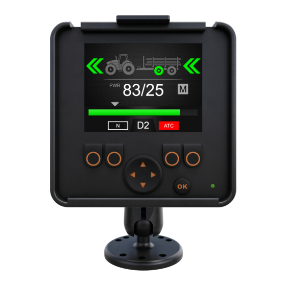
Main view elements Main view elements Main view at the initial state You can manage the operating functions from the main view. Figure 5. The main view after the power-up. The system is in the freewheeling mode. If the system does not have the auxiliary valve control, the AUX icon does not show. If the system has the 2-speed motors, the D2 icon shows. -
Page 15: Tractive Power And Hdc Level Indication
Main view elements 3: Sensor_failure_pressure_A 0/50 Figure 6. Status bar - Alarms and warnings. Tractive power and HDC level indication Tractive power level is shown on a scale of 0 -100%. Full power level is related to the maximum pressure level specified in the parameters. If the system has the HDC function (Hill descent control), the HDC level is also related to the maximum pressure level specified in the parameters. -
Page 16: Operating Mode Indication
Main view elements Measured level: • The number shows the measured val- • The colored power bar below the num- bers shows the measured value: • Green: PWR • Red: HDC. Measured and set values are percentages from the maximum pressure level that is specified in the settings (Maximum pressure level [bar]). - Page 17 Main view elements Current gear Operating mode icons • N: Freewheeling The icons come into view to show system mode and mode changes: • D1: Drive forward, speed range 1 • D2: Drive forward, speed range 2 • N: Freewheeling is active •...
-
Page 18: Operating Functions
Operating functions Operating functions Tractive power level selection You can use the arrow buttons to change the power level (left, to decrease the level or right, to increase the level). Power levels are 0, 25, 50, 75 and 100% of the maximum level. -
Page 19: Braking In Driving Mode
Operating functions Note: Do not use the driving modes in road traffic. 49/50 49/50 0/50 0/50 49/50 Figure 10. Operating mode selection. Automatic freewheeling (N) If the pressure level is not sufficient due to increased driving speed, the system automatically switches to the freewheeling mode. The parameter table (see chapter User parameters on page 25) gives the... - Page 20 Operating functions 8/25 Figure 11. Braking in driving mode. The system with the HDC function (Hill descent control) If the driving mode is either forward or reverse, the HDC function activates when the tractor brakes. The HDC text comes into view and the power bar color changes to red. When the HDC function operates the values shown on the display represent the intensity of the HDC function instead of the tractive power.
-
Page 21: Assisting Traction Control (Atc), (F3)
Operating functions 32/38 Figure 12. Braking in driving mode with the HDC function. Assisting traction control (ATC), (F3) The assisting traction control (ATC) helps the tractor to move in difficult conditions. The ATC function restricts the flow to the wheels that do not have enough traction. This increases the torque on the wheels that have more traction. - Page 22 Operating functions 43/50 Figure 13. Assisting traction control (ATC), (F3). The value of the parameter ATC max. time [s] has an effect on how the ATC function operates: • Value = 0: The ATC is on continuously during the drive. •...
-
Page 23: Auxiliary Valve Control (Aux), (F1) (Option)
Operating functions Note: Use the ATC when you drive on difficult terrain and on soft grounds. Auxiliary valve control (AUX), (F1) (option) Push the F1 button to toggle the auxiliary valve on and off. You can activate the AUX valve when the system is in the freewheeling (N) mode. The driving modes are not available while the AUX valve is activated. - Page 24 Operating functions Locked: hold OK to unlock Figure 15. Keypad lock. Danger: Make sure that you lock the keypad when you drive on road. Operation manual...
-
Page 25: User Parameters
User parameters User parameters Adjust the listed parameters before you use the system for the first time. Control systems with the HDC function (Hill descent control) have two pages of user parameters. Parameter Description Possible values 2-speed function Shows if the 2-speed function is 0 / 1 available to use(speed range selec- 0: No 2-speed function. - Page 26 User parameters Parameter Description Possible values Power change Ramp time that has an effect on the 0 - 4 ramp power level adjustment from the 0: The shortest time – fastest pow- display. er level change. 4: The longest time – the smooth- est power level change.
- Page 27 User parameters Parameter Description Possible values HDC level 1, pres- HDC power control setting, level 1 The minimum permitted value is 1. sure [bar] (weakest slowing power). The maximum permitted value is 100 or the value of the parameter Maximum pressure level [bar]. HDC level 2, pres- HDC power control setting, level 2.
-
Page 28: Troubleshooting
Troubleshooting Troubleshooting The status bar at the top of the main view shows all alarms and warnings. The table that follows gives the causes of the alarms and warnings, and procedures to correct them. Table 1: Fault messages. Alarm/warning Cause Procedures message 1: Coil_fail-... - Page 29 Troubleshooting Alarm/warning Cause Procedures message 6: Pressure_low The working pressure decreases The driving speed is too high for the below the specified minimum pres- drive. Use D2 driving mode for sure value during the drive and the higher speed. system automatically switches to If the warning comes on when the the freewheeling mode.
- Page 30 Troubleshooting Alarm/warning Cause Procedures message 12: CAN_connec- 4WD: No CAN connection between Examine the CAN cable between tion_break the primary control device and the the control devices. auxiliary control device. 13: Coil_fail- HDC: PDB2 valve solenoid control Do the same checks as with alarms ure_PDB2 error.
-
Page 31: Display Status Indicator Led
Troubleshooting Display status indicator LED Figure 16. Display status indicator LED. Color/status Description No LED No operating voltage Orange, 1 flash Device starts Green, 5 Hz The device has no software Green, 2 Hz Usual status Green, continuous Software error Red, 5 Hz Too low operating voltage, software stops Red, continuous... - Page 32 Troubleshooting LED/status Description PWR, 5 Hz The device has no software PWR, 2 Hz Usual status PWR, continuous Software error PWR, 10 Hz Software error Red, 5 Hz Too low operating voltage, software stops Red, continuous Dangerous device error Segment display text, 2WD-system Display text Description Empty, no text...
- Page 33 +358 20 755 0755 P.O. Box 633, FI-40101 JYVÄSKYLÄ, FINLAND www.blackbruin.com info@blackbruin.com All the information contained in this publication is based on the latest information available at the time of publication. Black Bruin Inc. reserves the right to make changes without prior notice.
Need help?
Do you have a question about the CTR101 and is the answer not in the manual?
Questions and answers