Table of Contents
Advertisement
Quick Links
Advertisement
Table of Contents

Related Manuals for Black Bruin On-Demand

Summary of Contents for Black Bruin On-Demand
- Page 1 Product manual On-Demand Drive System CTR101 / CTR201 and CVM120 / CVU200 valves...
-
Page 2: Table Of Contents
Warranty................................5 Product identification............................. 5 Revision comments............................5 Safety instructions................6 Warning symbols..............................6 Product description................7 Main components of the On-Demand Drive System................7 Control systems............................... 8 Working principle..............................8 Driving mode..............................8 HDC function (Hill descent control) (option).....................9 Freewheeling mode............................10 System design.................. 11 Hydraulic motors.............................11... - Page 3 Contents Installation and commissioning............ 28 Installation and the connections.......................28 Power-up the control system........................30 Air bleeding procedure..........................31 Examine the connections........................... 32 Test drive................................. 32 Technical data................. 34 Control device..............................34 Display................................35 Display mount..............................36 Pressure sensor............................. 37 CVM120 2WD valve............................38 CVM120 2WD HDC valve..........................
-
Page 4: General Instructions
Black Bruin On-Demand Drive System is very applicable for equipment that periodically requires additional power and is towed without hydraulics. Black Bruin On-Demand Drive System is designed for off-road driving and must be powered off when you drive in road traffic. -
Page 5: Warranty
General instructions Warranty Check the package and the product for transport damage when receiving goods. The package is not meant for long term storage; protect the product appropriately. Do not dismantle the product. The warranty is void if the product has been disassembled. -
Page 6: Safety Instructions
Safety instructions Safety instructions The instructions that follow apply to all procedures related to the product. Read these instructions fully and follow them carefully. • Use necessary personal protective equipment when you do work with the product. • Use correct support with the product. Make sure that the product cannot accidentally fall or turn. -
Page 7: Product Description
Product description Product description Main components of the On-Demand Drive System Valve • Motor mode changes between driving and freewheeling • Driving direction change • Displacement control of two-speed motors • Pressure level (tractive power) adjustment • Assisting traction control (ATC) •... -
Page 8: Control Systems
If necessary, manual operation of the system is also available. Working principle The Black Bruin On-Demand Drive System can use hydraulic motors in the operating modes that follow: • Driving mode • Driving mode with HDC function (Hill descent control) (option) •... -
Page 9: Hdc Function (Hill Descent Control) (Option)
Product description • Going across obstacles • Driving on slippery or soft surfaces. HDC function (Hill descent control) (option) The HDC function helps when you drive the vehicle down on steep slopes, in both forward and reverse driving modes. When the HDC function is active, the wheel motors resist the wheel movement to the driving direction. -
Page 10: Freewheeling Mode
Product description Freewheeling mode In the freewheeling mode you can freewheel the motors without energy loss or overheating problems (stationary cylinder block - no centrifugal forces), even at high speeds. You can engage the drive again during movement when the speed is in the working range. -
Page 11: System Design
• Not compatible: • Spring-loaded multidisc brake. We recommend to use B200-series 2-speed motors for the On-Demand Drive System. Please contact the manufacturer or their representative who will help you to select the most applicable motor model for your application. -
Page 12: Valves
System design Valves 4.2.1 Valve models Model series CVM120 / 2WD CVU200 / 2WD CVM120 / 4WD Maximum flow rate (P->T) 120 l/min 200 l/min 2WD: 55 l/min / motor 100 l/min / motor Flow-rate limitation (in ATC function 40 l/min / motor (option) * 80 l/min / motor (option) * (A1-B1 / A2-B2)* 4WD: 28 l/min / motor... -
Page 13: Hydraulic System
System design Hydraulic system When you plan to use the CVM120/CVU200 valves, make sure that: • You use the CVU200 valve only in a system with a load-sensing pump and an LS line. • The CVM120/CVU200 valves are not applicable to use in closed-circuit hydraulic systems. -
Page 14: Hydraulic Connections
System design Hydraulic connections Figure 3. Connection diagram, 2WD. Valve 2 Motor, right 3 Motor, left 4 Hydraulic lines to the tractor Figure 4. Connection diagram, 4WD. Valve 2 Motor, right 3 Motor, left 4 Hydraulic lines to the tractor The drain line (C) has a mark (C2) in motors with flushing line (C1). - Page 15 System design Make sure that you verify the rotating direction of the left motor from the datasheet of the motor. Make sure that you connect the left motor correctly. Refer to the table that follows for the left motor connections. Driving direction.
- Page 16 System design the CVM120/CVU200 valve (2) or to the crane valve (3). If the vehicle has a load- sensing system, a shuttle valve (4) is also necessary. The shuttle valve lets the selected valve to control the working pressure level. Figure 5.
-
Page 17: Port Pairs
System design Port pairs The port pairs of valve lines A and B have A1/B1 and A2/B2 marks. Always connect each motor to a port pair as shown in the figure below. Figure 6. The port pairs. You can connect left and right side motors to one of the two port pairs. Product manual... -
Page 18: Control System
Control system Control system Model series of the control system The table that follows shows the differences between the two control system models, CTR101 and CTR201. The CTR201 control system can use the vehicle speed and direction information through the tractor ISOBUS implement-connector to control the driving functions. CTR101 CTR201 Connection to tractor ISOBUS implement-connector... -
Page 19: Product Identification Code
The table that follows gives the identification codes for the model series of the CTR101 and CTR201 control system. You can use the identification code to order the control system. CTR101/CTR201 SERIES MODEL CODE AAAAAA-BB-CCC-DDD-EE-FF On-Demand Drive control-system series CTR101 and CTR201 AAAAAA: Control AAAAAA-BB-CCC-DDD-EE-FF CTR101 CTR201... -
Page 20: Control System Connection Diagrams
Control system • Attach the control device near the valve and in a location where the mechanical shocks or wear cannot cause damage to it. If necessary, use mechanical protection. • Make sure that the installation location of the cables: •... - Page 21 Control system CTR101: Power cable CTR201: Power / ISOBUS cable See chapter Power cable types page 24. Resistor plug External alarm signal cable (accessory) HDC / AUX valve cable (accessory) 2 / 1 +12V +12V 1 PDB2 CAN IN CAN OUT CAN IN CAN OUT 12 V DC...
-
Page 22: Display Cable With Extension
Control system 5.3.3 Display cable with extension Display cable Connects the display to the control device Cable type Straight Length 10 m Head 1 design Deutsch DT06-6S connector that connects to the control device. Head 2 design M12x1 5-pin that connects to the display extension cable. Can also con- nect directly to the display in fixed installations. -
Page 23: Brake Signal Cable
Control system 5.3.5 Brake signal cable Connects the brake signal to the control device Cable type Straight Length 10 m Head 1 design Deutsch DT06-6S connector that connects to the control device Head 2 design Free conductors (2): • Brown (+) – Brake signal •... -
Page 24: Controller Link Cable
Control system 5.3.8 Controller link cable Only in 4WD systems: Connection between the two control devices Cable type Straight Length Each branch 1 m Head 1 & 2 design Deutsch DT06-6S connectors that connect to the two control devices 5.3.9 Power cable types Power cable for CTR101 (Supply kit P10 in the identification code) Head 1 design... -
Page 25: Protective Caps
Control system Power / ISOBUS cable for CTR201 (Supply kit I10 in the identification code) Use the information that follows when you plan the installation: • The branching tube diameter is 30 mm • When you thread the cable, the hole size for the AMP connector and the TBC connector must be a minimum of 40 mm. -
Page 26: Hdc / Aux Valve Cable (Optional Accessory)
Control system 5.3.12 HDC / AUX valve cable (optional accessory) Part number 50243003 Connects the HDC valve and/or the auxiliary valve. This cable is necessary if you plan to use the HDC valve and/or the auxiliary valve. Cable type Y cable Length Each branch 1 m Head 1 design... -
Page 27: External Alarm Input Cable (Optional Accessory)
Control system 5.3.14 External alarm input cable (optional accessory) Part number 50248000 If the system detects an alarm signal, the external alarm signal con- nection prevents the use of the driving functions. Examples for the external alarm signal uses are connections to: •... -
Page 28: Installation And Commissioning
Installation and commissioning Installation and commissioning Installation and the connections Examine the preferred rotating direction of the hydraulic motors to select the correct motors for the left and the right side. Install the motors. Refer to the motor manual for the correct installation method. Do not install the wheels at this time. - Page 29 Installation and commissioning 43 mm DW Valve adjustment when the valve is connected to the LS line.* There is a small gap (2) between the adjustment knob and the locking nut, although the valve is in the fully closed position. 49 mm DW Valve adjustment when the LS line is closed with a plug.* * Tighten the lower nut.
-
Page 30: Power-Up The Control System
Installation and commissioning 11. Make sure that you use the correct CAN plug for the open CAN OUT socket. 12. CTR201 only: Connect the terminating bias circuit connector to the corresponding branch of the ISOBUS / power cable (see chapter Power cable types on page 24). -
Page 31: Air Bleeding Procedure
Installation and commissioning If the information on the display(s) is different, the system is not operating correctly. Examine the cable connections. Air bleeding procedure In the air bleeding procedure the motor housing is fully filled with the hydraulic fluid. The housing has air bleeding screws to remove the air from the housing. The control system can help in the procedure. -
Page 32: Examine The Connections
Installation and commissioning To air bleed the 2-speed control pilot-line, do the steps that follow: Loosen the Y-port fittings on the motor. Select the D2 speed range on the control system. Drive the motor forward. When the hydraulic fluid flows through the fitting, tighten the connections back to the same tightness as before. - Page 33 Installation and commissioning Note: • The tractors have different pump models that operate differently. Thus, when you connect the system to the tractor you use, you must do more detailed testing and set the parameters correctly. More specific information about the parameters, the alarm messages and the troubleshooting instructions are in the CTR101 or CTR201 Operation manual.
-
Page 34: Technical Data
Technical data Technical data Control device Figure 11. Control device, main dimensions. External dimensions without cables 234.2 mm x 76 mm x 40.5 mm (A x B x C) Control device attachment point dimensions 52 mm x 205.5 mm (D x E) Protection class IP 65, connectors attached: IP 67 Operating temperature... -
Page 35: Display
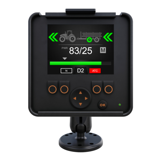
Technical data Display Figure 12. 2.8" color display, main dimensions. External dimensions (A x B x C/D) 87.5 mm x 87.5 mm x 37.8 mm /31.3 mm Opening size in panel installation 81.5 ± 0.5 mm x 81.5 ± 0.5 mm Protection class IP 67 (installed) / IP 65 (not installed) Operating temperature... -
Page 36: Display Mount
Technical data Display mount Part Material External dimensions Mounting arm Aluminum black anodized A/B: 128 mm/95 mm 2 Mounting plate Aluminum black anodized Diameter C: 62 mm 3 Display carrier Plastic black D/E x F: 68 mm/62 mm x 93 mm 4 Ball Rubber Product manual... -
Page 37: Pressure Sensor
Technical data Pressure sensor Figure 13. Pressure sensor, main dimensions. External dimensions (A x B/D) 71.5 mm x 21.8 mm / 25.4 mm Measurement range 0...400 bar Cable connector Deutsch DT04-3S Process connection (C) G1/4" Product manual... -
Page 38: Cvm120 2Wd Valve
Technical data CVM120 2WD valve Figure 14. CVM120 2WD valve, main dimensions. Order code CVM120-A1H0T0V12S00 External dimensions (A x B) 196 mm x 307 mm External dimensions (C x D) 307 mm x 221 mm Weight 26.5 kg Maximum pressure level 350 bar Maximum flow rate 120 l/min... -
Page 39: Cvm120 2Wd Hdc Valve
Technical data CVM120 2WD HDC valve Figure 16. CVM120 2WD HDC valve, main dimensions. Order code CVM120-A1H1T0V12S00 External dimensions (A x B) 196 mm x 307 mm External dimensions (C x D) 307 mm x 276 mm Weight 33.5 kg Maximum pressure level 350 bar Maximum flow rate... -
Page 40: Cvm120 4Wd Valve
Technical data CVM120 4WD valve Figure 18. CVM120 4WD valve, main dimensions. Order code CVM120-A2H0T0V12S00 External dimensions (A x B) 196 mm x 307 mm External dimensions (C x D) 307 mm x 353 mm Weight 42.2 kg Maximum pressure level 350 bar Maximum flow rate 120 l/min... -
Page 41: Cvm120 4Wd Hdc Valve
Technical data CVM120 4WD HDC valve Figure 20. CVM120 4WD HDC valve, main dimensions. Order code CVM120-A2H1T0V12S00 External dimensions (A x B) 196 mm x 305.5 mm External dimensions (C x D) 305.5 mm x 408.3 mm Weight 49.3 kg Maximum pressure level 350 bar Maximum flow rate... -
Page 42: Cvu200 Valve
Technical data CVU200 valve Figure 22. CVU200 valve, main dimensions. Order code CVU200-A1H0T0V12S00 External dimensions (A x B) 228 mm x 315 mm External dimensions (C x D) 315 mm x 240 mm Weight 36.0 KG Maximum pressure level 350 bar Maximum flow rate 200 l/min Operating voltage... - Page 43 +358 20 755 0755 P.O. Box 633, FI-40101 JYVÄSKYLÄ, FINLAND www.blackbruin.com info@blackbruin.com All the information contained in this publication is based on the latest information available at the time of publication. Black Bruin Inc. reserves the right to make changes without prior notice.
Need help?
Do you have a question about the On-Demand and is the answer not in the manual?
Questions and answers