Table of Contents
Advertisement
Quick Links
Advertisement
Table of Contents
Troubleshooting

Related Manuals for WeldKing MULTISONIC220


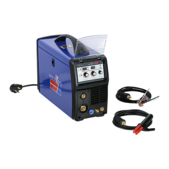
Summary of Contents for WeldKing MULTISONIC220
- Page 1 MULTISONIC220 MIG (GMAW) Flux cored (FCAW) TIG (GTAW) STICK (SMAW) Arc Welding Power Source Serial Number: _________________________________ Where Purchase: _________________________________ Date of purchased: _________________________________...
- Page 2 READ INSTRUCTIONS! Consult the Owner’s Manual for welding safety precautions. Use only genuine replacement parts While the information contained in this Manual represents the Manufacturer's best judgment, the Manufacturer assumes no liability for its use. Model Name: Date of purchased: Serial Number: Where Purchase:...
- Page 3 NOTES WELDKING® MultiSonic220 power source...
- Page 4 MultiSonic - 220 NOTES WELDKING® MultiSonic220 power source...
- Page 5 NOTES WELDKING® MultiSonic220 power source...
-
Page 7: Table Of Contents
Table of Contents SECTION 1 SAFETY PRECAUTIONS ................... 1 SECTION 1 CONSIGNES DE SÉCURITÉ ................... 1 1-1. Symbol Usage Symboles utilisés ..............1 1-2. Arc welding Hazards Dangers relatifs au soudage à l’arc ....... 1 1-3. Safety Standards Normes de sécurité ............6 1-4. -
Page 8: Safety Precautions
MultiSonic - 220 SECTION 1 SAFETY PRECAUTIONS SECTION 1 CONSIGNES DE SÉCURITÉ 1-1. Symbol Usage Symboles utilisés Means Warning! Watch Out! There are possible hazards with this procedure! The possible hazards are shown in the adjoining symbols. Symbole graphique d’avertissement ! Attention ! Cette procedure comporte des risques possibles ! This group of symbols means Warning! Watch Out Les dangers éventuels sont représentés par les symboles... - Page 9 MultiSonic - 220 Do not touch electrode if you are in contact with the work, conducteur de mise à la terre approprié et contre-vérifier ground, or another electrode from a different machine. les connexions. Do not touch electrode holders connected to two welding ...
- Page 10 MultiSonic - 220 CYLINDERS can explode if Ne pas placer l’appareil sur, au-dessus ou à proximité de damaged. surfaces inflammables. LES BOUTEILLES peuvent exploser Ne pas installer l’appareil à proximité de produits si elles sont endommagées. inflammables. Shielding gas cylinders contain gas under high ...
- Page 11 MultiSonic - 220 comprimé, l’équipement connexe et le dépliant P-1 de la CGA (Compressed Gas Association) mentionné dans les principales normes de sécurité. FALLING UNIT can cause injury. OVERUSE cause OVERHEATING. L’EMPLOI LA CHUTE DE L’APPAREIL peut EXCESSIF peut SURCHAUFFER blesser.
- Page 12 MultiSonic - 220 READ INSTRUCTIONS. LIRE LES INSTRUCTIONS. Lire le manuel d’utilisation avant d’utiliser ou d’intervenir sur l’appareil. Utiliser uniquement des pièces de rechange. Consult the Owner’s Manual for welding safety precautions. Use only genuine replacement parts Page 5 Manual no.
-
Page 13: Safety Standards Normes De Sécurité
MultiSonic - 220 1-3. Safety Standards Normes de sécurité Safety in Welding, Cutting, and Allied Processes, ANSI Standard Code for Safety in Welding and Cutting, CSA Standard W117.2, Z49.1, from Global Engineering Documents (phone: from Canadian Standards Association, Standards Sales, 178 1-877-413-5184, website: www.global.ihs.com). -
Page 14: Section 2 Packing List
MultiSonic - 220 SECTION 2 PACKING LIST MultiSonic220 package (Part No: WMP02000 ) Description Part no Quantity MultiSonic220 Power source come with 10 ft. (3 M) Power cord and molded NEMA 6-50P 230V AC Plug WeldKing NT1-3E industrial Welding gun-Tweco KAM31003 style consumables, 10ft(3M) -
Page 15: Section 3 Basic Information
MultiSonic - 220 SECTION 3 BASIC INFORMATION 3-1. Power source specifications MultiSonic220 package (Part No: WMT05000 ) AC 115V,60Hz,1 phase AC (208)V/230V,60Hz, 1 phase Power supply Welding STICK STICK Process Input Amps @ Maximum 22.4 17.5 18.4 15.9 11.8 output(A) Rated input (KW) -
Page 16: Mig Torch Specifications
MultiSonic - 220 Power source 15(33lbs) weight (KG) Packing dimension 63x38x52(24.8x15x20.4in) (HxWxD)(CM) Packing 23(50.7lbs) weight(KG) Table 3.1 3-2. MIG torch specifications Model NT1-3E (Part no. KAM31003 ) Rated currency(A) 200A/CO2,180A/MIX Rated duty cycle (%) Rated voltage(V) <=113V Cooling style Air cooled Air consumption (l/min) 10-18 3(10ft) - Page 17 MultiSonic - 220 FCAW – Connect to euro Connect to DCEN- Self-shielding connection positive(+)output terminal Straight wire- no shielding Polarity STICK process DCEP – Connect to positive(+) Connect to Reverse output terminal negative(-)output terminal polarity TIG process Connect to negative(-) Connect to DCEN-...
-
Page 18: Installations
MultiSonic - 220 SECTION 4 INSTALLATIONS 4-1. MIG welding connection diagram MultiSonic220 (115v input) Gauge To gas regulator Cylinder To main power To 115 volt, 20 ampere individual branch circuit MIG torch NT1-3E Earth clamp Figure 4.1 Page 11 Manual no. - Page 19 MultiSonic - 220 MultiSonic220 (208/230v input) Gauge Cylinder MIG torch NT1-3E To gas regulator To main power Earth clamp Figure 4.2 Manual no. WDT90100 Page 12...
-
Page 20: General Installation Procedure For Mig Welding
MultiSonic - 220 4-2. General installation procedure for MIG welding 4-2.1.Welding machine should be installed in a stable position and with good ventilation. Avoid direct sun outdoors or rain. Place at a distance of 12” (300mm) or more from walls or similar that could restrict natural air flow for cooling. Avoid transport in invert or side position. - Page 21 MultiSonic - 220 Figure 4.3 Installing 8" (200mm) Diameter Spool Figure 4.4 Installing 4" (100mm) Diameter Spool 4-3.2.The drive roll has two grooves; the small groove feeds 0.035 in. diameter wire, the large groove feeds 0.045 in. wire. The groove nearest the gear motor feeds the wire. 4-3.3.Release pressure drive roll assembly and lift upward.
-
Page 22: How To Adjust Wire Feed Pressure
MultiSonic - 220 4-4. How to Adjust wire feed pressure Make sure that the wire moves smoothly through the wire guide. Then set the pressure of the wire feeder’s pressure rollers. It is important that the pressure is not too high. Feed out the wire against an insulated object, e.g. -
Page 23: How To Install Spool Gun(Optional)
MultiSonic - 220 4-5. How to Install spool gun(optional) MultiSonic220 use WeldKing® SpoolKing-24DL (Part no. 07NS1010) only. Use other model may not work properly. Figure 4.6 Connect spool gun to the euro receptacle. Connect 9 pin control cable to control receptacle located at front penal penal. -
Page 24: Tig(Dc) Welding Connection Diagram
MultiSonic - 220 4-6. TIG(DC) welding connection diagram MultiSonic220 (115v input) Gauge To gas regulator To main power Cylinder To 115 volt, 20 ampere individual branch circuit Gas hose Control cable TIG torch MUST Earth clamp CONNECTED TO THE NEGTIVE! Figure 4.7... - Page 25 MultiSonic - 220 MultiSonic220 (208/230v input) Gauge Cylinder Power cord Gas hose Control cable torch MUST CONNTECT Earth NEGTIVE! Figure 4.8 Manual no. WDT90100 Page 18...
-
Page 26: General Installation Procedure For Tig Welding
MultiSonic - 220 4-7. General installation procedure for TIG welding 7-2.1.Welding machine should be installed in a stable position and with good ventilation. Avoid direct sun outdoors or rain. Place at a distance of 12” (300mm) or more from walls or similar that could restrict natural air flow for cooling. Avoid transport in invert or side position. -
Page 27: Stick Welding Connection Diagram
MultiSonic - 220 4-8. STICK welding connection diagram MultiSonic220 (115v input) To 115 volt, 20 ampere individual branch circuit Power Electrode holder Cord Earth clamp Figure 4.9 Manual no. WDT90100 Page 20... - Page 28 MultiSonic - 220 MultiSonic220 (208/230v input) Power cord Electrode holder Earth clamp Figure 4.10 Page 21 Manual no. WDT90100...
-
Page 29: General Installation Procedure For Stick Welding
MultiSonic - 220 4-9. General installation procedure for STICK welding 7-4.1.Welding machine should be installed in a stable position and with good ventilation. Avoid direct sun outdoors or rain. Place at a distance of 12” (300mm) or more from walls or similar that could restrict natural air flow for cooling. Avoid transport in invert or side position. -
Page 30: Electric Service Guide
MultiSonic - 220 4-10. Electric service guide CAUTION! WARNING: THIS WELDING MACHINE MUST BE CONNECTED TO POWER SOURCE IN ACCORDANCE WITH APPLICABLE ELECTRICAL CODES AVERTISSEMENT: LE RACCORDEMENT DE CETTE MACHINE DE SOUDAGE Á L’ALIMENTATION DOIT ÉTRE CONFORME AUX CODES D’ ÉLECTRICITÉ PERTINENTS Input voltage(V) 208/230... -
Page 31: Extension Welding Cable Selection Chart
MultiSonic - 220 4-11. Extension Welding Cable Selection Chart CAUTION! Use shortest cable possible. Turn off power before connecting to weld output terminals! Welding cable size in Maximum total cable (Copper) length in weld circuit allowed in Ft(M) AWG (mm Welding Amperes (A) 6(13) 260(80) -
Page 32: Section 5 Operation
MultiSonic - 220 SECTION 5 OPERATION 5-1. Power source panel layout and description 1. MIG process indication light 10. Slope down display indication light 2. STICK process indication light 11. Arc force display indication light 3. LIFT-TIG process indication light 12. - Page 33 MultiSonic - 220 Manual no. WDT90100 Page 26...
- Page 34 MultiSonic - 220 18. Positive output connect 24. Remote on/off 19. Euro MIG torch connection 25. Spool gun on/off 20. 9 pin control port 26. Burn back control (0-1s) 21. Negative output connect 27. Run-in control (0-2s) 22. Gas outlet to torch (MIG/TIG) 28.
-
Page 35: Operation(Mig)
MultiSonic - 220 5-2. Operation(MIG) USE SINGLE PHASE 115V/208V/230V POWER SUPPLY. 5-2.1.Switch on the power source 5-2.2.Connect up the shielding gas, torch and work lead to power source according to figure 4.1 and 4.2, make sure connections are firm and reliable. 5-2.3. -
Page 36: Operation(Tig)
MultiSonic - 220 5-2.9. Push up “jog” switch to momentarily feed welding wire at speed set on Wire Speed control without energizing welding circuit or shielding gas valve. Push up “purge” switch to momentarily energize gas valve to purge air from gun or adjust gas regulator. 5-2.10.Turn on the gas valve, adjust gas volume to 3-5L/MIN. -
Page 37: Operation(Stick)
MultiSonic - 220 5-3.7.Turn on the gas valve on the torch; adjust gas volume to 3-5L/MIN. check if there is gas leaking. 5-3.8. Press down TIG torch trigger, touch tungsten electrode to workpiece at weld start point. Hold electrode to Workpiece for 1-2 seconds, and then slowly lift electrode. Arc is formed when electrode is lifted. -
Page 38: Operate With Remote Current Control Device Connected
MultiSonic - 220 workpiece, use a quick twist to free it. 5-4.7.At the end, turn off welding power source and wall switch. 5-5. Operate with remote current control device connected The machine can connect to foot pedal (part no. 07002510) or torch with remote current control through 9 pin control receptacle at the front panel. -
Page 39: Welding Parameter Selection Chart
MultiSonic - 220 5-6. Welding Parameter selection chart The setting listed below is just for initial commission of the machine. The parameter can be refined during welding. Figure 5.3 Manual no. WDT90100 Page 32... -
Page 40: Spool Gun/Tig Torch /Foot Petal Control Connection Pin Definition
MultiSonic - 220 Spool gun/TIG Torch /Foot petal control connection pin definition Figure 5.4 Socket pin Function Notes Spool gun motor (-) Trigger switch Trigger switch Spool gun motor (+) C.C.W potentiometer(+) spool gun / TIG torch C.W potentiometer(-) spool gun / TIG torch TIG torch wiper potentiometer current MIG Spool gun wiper potentiometer... -
Page 41: Section 6 Trouble Shooting
MultiSonic - 220 SECTION 6 TROUBLE SHOOTING 6-1. General trouble shooting Problem Cause Solution Power Indication lamp does not on Loose contact at Check contact after switch on the main switch input lead situation Lamp malfunction, Check contact poor contact situation. - Page 42 MultiSonic - 220 Input voltage is too Use under rate high input voltage Power supply switch jump Rectifier short Check and circuit replace Main transformer Check and short circuit replace Control transformer Check and short circuit replace Solenoid valve Check and short circuit replace Cooling fan short...
-
Page 43: Gmaw/Fcaw Welding Trouble Shooting
MultiSonic - 220 6-2. GMAW/FCAW welding trouble shooting Problem Cause Solution No gas flow out after Gas pressure not enough Check gas pushing the gun trigger pressure Poor gas hose connection Check gas connection Gun trigger failure Check gun trigger Solenoid valve failure Check and replace Solenoid valve... - Page 44 MultiSonic - 220 Welding cable broken or Check the poor contact connection Gun trigger wire broken Replace cable Gun cable broken Replace cable Voltage adjustment knob Check, repair, failure or poor contact replace Control transformer failure Check, repair, replace Main transformer failure or Check, repair, poor contact replace...
- Page 45 MultiSonic - 220 repair, replace the work piece surface Clean the contaminated by oil workpiece surface Poor contact inside the Check, repair, replace Arc ignited but the wire Rectifier tube failure Check, replace does not melt Output reactor failure Check, replace Output capacitor failure Check, replace Wire does not feed while...
-
Page 46: Stick/Tig Welding Trouble Shooting
MultiSonic - 220 Pressure roller deformed Check and replace Feeding motor failure Check and replace Current adjust potential Check and replace meter failure Circuit board plug socket Check and repair not properly contacted or replace Control circuit failure Check and repair or replace Welding hose deformed Check and replace... - Page 47 MultiSonic - 220 receptacle at machine connections Poor connection between Clean and tighten electrode hold and welding cable Failure of arc to ignite or Fuse melt or poor contact Check and repair does not ignite properly Main power switch failure Check, repair, replace Control circuit board failure...
- Page 48 MultiSonic - 220 Welding cable size or type See table 2.3 is not proper Electrode selection is not See Table 3.2 proper the work piece surface Clean the contaminated by oil workpiece surface Poor contact inside the gun Check, repair, replace Rectifier tube failure Check, replace...
-
Page 49: Maintenance
MultiSonic - 220 SECTION 7 MAINTENANCE Maintenance 7-1. Periodic maintenance is necessary for keeping the machine work properly. CAUTION! DISCONNECT POWER INPUT AND SWITCH OFF THE MAIN POWER SWITCH BEFORE START OF MAINTENANCE. Regular Check and Inspection for 6 Month Routine Maintenance for machine machine Blow out with dry clean pressure air or... -
Page 50: Safety Precaution
MultiSonic - 220 guide tube and feeding roller, clean and check if the feeding tube diameter is proper and is aligned with the center of the feeding roller. Also check if the feeding roller groove is same as the wire diameter and if there are objects inside groove. -
Page 51: Lens Shade Selector Guide
MultiSonic - 220 MUST BE PERFORMED BY QUALIFIED PERSONAL. Welders must be equipped with welding mask, gloves and tie the sleeves and collar properly. Use Table 6.4 to choose proper glass shade, also can reference to ANSI Z49.1 listed in Safety Standards. There should be an arc shield around welding field to protect others from arc shock. -
Page 52: Parts List
MultiSonic - 220 SECTION 8 PARTS LIST Item Order No. Description Note Handle Curve 301*90*66 black 8.253RM.003-B 1 use with S.004RM.719-K Right side penal 8.051RM.719 MIG180PFC MV 1 use with S.004RM.719-K Left side penal 8.050RM.719 MIG180PFC MV 1 Penal lock square 'MS725-2 chassis lock serial 7.686.300 1 ... - Page 53 MultiSonic - 220 Hinge CL204-6 black, 2 hinge seat, 1 7.686.080 pin, seat size:20*8*14mm 2 Use with MULTIMIG 200 PFC bottom plate 8.055RM.734 SYN HZ 1 Middle plate MULTIMIG 200 HZ penal, use 8.303RM.713 with S.004RM.713-AO 1 Feeding system Feeding system 7.710.076 1 ...
- Page 54 MultiSonic - 220 Omter φ21*6 , black cap/grey Knob 7.458.430 body,black needle 2 Omter φ16.3*16.5 , black Knob 7.458.420 cap/grey body,black needle 1 MULTIMIG 200 HZ penal used Penal mount plate 8.306RM.713 with S.004RM.713-AO 1 MULTIMIG 200PFC Base board(B.067RM.183-D) W.496RM.183-D front penal 1 ...
- Page 55 MultiSonic - 220 Y connection ODΦ8, IDΦ5 7.624.281 1 MULTIMIG200 Base board(B.067RM.205-D) W.496RM.205-D power pcb 1 Toggle switch(no 16A/250V used with 7.227.022 mark) 3.004RM.203 3.004RM.204 1 Toggle switch(no R9-32B/2A250V 1×2 7.227.017 mark) 1 Toggle switch(no R13 12A 125VAC 6A 250VAC 2*2 7.227RM.001-A mark) 1 ...
- Page 56 MultiSonic - 220 Quick restore diode STTH60W03CW 6 7.401.079 insulation block(4) polycarbonate 3 holes 12.5mm 8.713.184 12 Used with IGBT heat sink(3) S.004RM.251-E,section plate 8.422RM.206 7.800.136 1 Used with A-10 IGBT heat sink(4) S.004RM.251-E,section plate 8.422RM.207 7.800.136 1 Cold rolling plate 0.8 size A-11 Support pole 8.123RM.005...
- Page 57 MultiSonic - 220 Figure 8.1 Manual no. WDT90100 Page 50...
- Page 58 MultiSonic - 220 Wire driving system Figure 8.2 Item Description Order No. Motor #301 Name plate Spring washer type A10 GB/T894, 1-1986 Semi-circular key 3x3.7x10 GB/T1099-1979 Page 51 Manual no. WDT90100...
- Page 59 MultiSonic - 220 Pressure adjustment knob 816D.2 Pressure roll support 816.2-1 Pressure roller support sleeve 1 816.2-3 Round spring pin GB/T879, 2-2000 Rolling bearings 62002z GB/T246, 2-1994 Wire feeding tube component 805.3 Pressure roller support sleeve 2 816.2-4 Pressure roller support axle 816.2-2 Washer with notch8 GB/T896-1986...
- Page 60 MultiSonic - 220 MIG torch WeldKing® NT1-3E, Order No. KAM31003 Figure 8.3 Nozzles ITEM DESCRIPTION ORDER NO. Nozzle Self Insulated 21-37 Nozzle Self Insulated 21-50* Nozzle Self Insulated 21-62 Nozzle Self Insulated 21-37F Nozzle Self Insulated 21-50F Page 53 Manual no.
- Page 61 MultiSonic - 220 Nozzle Self Insulated 21-62F Nozzle Self Shielding LA8201 Table 8.3 Contact Tips ITEM DESCRIPTION ORDER NO. Contact Tip 0.023”/0.6mm Ecu 11-23 Contact Tip 0.030”/0.8mm Ecu 11-30 Contact Tip 0.035”/0.9mm Ecu 11-35* Contact Tip 0.040”/1.0mm Ecu 11-40 Contact Tip 0.045”/1.2mm Ecu 11-45 Table 8.4 Liners...
- Page 62 MultiSonic - 220 Handle locking Nut EH1111 Gun Handle (Front) EH1101 Trigger Assembly EJ0003 Gun &Cable Assembly 3M TEL1030 Rear spring cable support ES2201 Gun plug housing EH2201 Screw(M4X6) EH2211 Rear lock nut EP2001 Euro connector(Tweco) ETU001 O ring 4x1 Q504010 O ring 4x8 Q504018...
- Page 63 MultiSonic - 220 NOTES WELDKING® MultiSonic220 power source Manual no. WDT90100 Page 56...
-
Page 64: Electric Diagram
MultiSonic - 220 SECTION 9 ELECTRIC DIAGRAM Figure 9.1 Page 57 Manual no. WDT90100... -
Page 65: Warranty Policy
(2) All limited warranties are void for, and Malo Welding registration card included in the package to Malo Welding Products Ltd.(WeldKing® ) does not warrant in any way, any Products Ltd.(WELDKING® ) right after the purchase. When product that evidences misapplication, improper installation,... -
Page 66: Section 11 Authorized Service Center
MultiSonic - 220 AUTHORIZED SERVICE CENTER SECTION 11 Please go to our website www.weldking.com to fill the warranty registration form. Malo Welding Products Ltd. will not distribute of disclose customer's private information to any third party and will not sent promotion material to the customer. - Page 67 MALO WELDING PRODUCTS LTD. 12-3400 Ridgeway Drive, Mississauga, Ontario, L5L 0A2, Canada Tel: 1 866 686 5088 Fax: 1 866 686 5090 Website: www.weldking.com Printed December 1st, 2018...
Need help?
Do you have a question about the MULTISONIC220 and is the answer not in the manual?
Questions and answers