Table of Contents
Advertisement
Quick Links
Advertisement
Table of Contents

Related Manuals for Outform iDISPLAY Adult Height

Summary of Contents for Outform iDISPLAY Adult Height
- Page 1 Adult Height Child Height Counter Height Wall mount(Optional) User Manual...
-
Page 2: Table Of Contents
Table of Contents Important Notices ................2 Copyright Information ................2 Safety and Warning Information ............3 Package Contents ................4 Adult Height ................... 4 Child Height ................... 5 Counter Height ..................6 Product Diagram ................7 Adult Height ................... 7 Child Height ................... 9 Counter Height .................. -
Page 3: Important Notices
Copyright Information Copyright © 2020 Outform. All rights reserved. All intellectual property rights in this publication are owned by Outform and protected by applicable copyright laws and international treaty provisions. Outform retains all rights not expressly granted. No part of this publication may be reproduced in any form whatsoever or used to make any derivative work without prior written approval by Outform. -
Page 4: Safety And Warning Information
Safety and Warning Information NOTE This mark is applied to indicate that the equipment conforms to European safety and electro-magnetic compatibility standards. WARNING! Main Supply: This equipment is designed to operate from a 100-240 Volt, 50/60Hz AC power supply. The use of other power sources may damage this equipment. Check that the voltage marked on the rating plate located at the rear of the power adaptor states 100-240V. -
Page 5: Package Contents
Package Contents Adult Height USB Hub Mini mouse Adult Thermometer 3M long PSU with Reflective floor sticker x4pcs Stand different region plugs Screw Driver Optional: Wall bracket M3 Screw x3pcs Self-tapping screw and expansion screw x6pcs... -
Page 6: Child Height
Package Contents Child Height USB Hub Mini mouse Child Thermometer 3M long PSU with Reflective floor sticker x4pcs Stand different region plugs Screw Driver Optional: Wall bracket M3 Screw x3pcs Self-tapping screw and expansion screw x6pcs... -
Page 7: Counter Height
Package Contents Counter Height USB Hub Counter Mini mouse Thermometer Stand Screw Driver 3M long PSU with Reflective floor sticker x4pcs different region plugs Optional Wall bracket M3 Screw x3pcs Self-tapping screw and expansion screw x6pcs... -
Page 8: Product Diagram
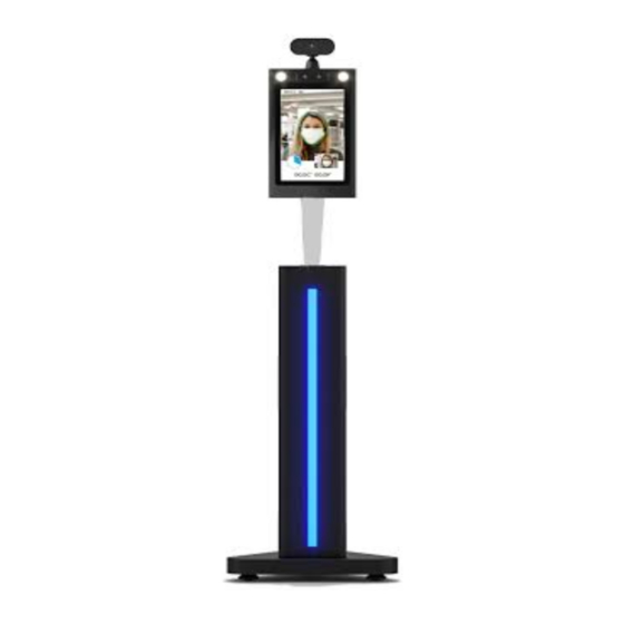
Product Diagram Adult Height... - Page 9 Product Diagram Description Infrared temperature measurement module Indicator light, has White/Green/Red three modes Wide dynamic camera 8 inch IPS screen Speaker Hidden USB interface DC 12V 2A RED labeled RJ45 YELLOW labeled BLUE labeled USB 2.0 * 10 Relay GREEN labeled * 11 Wiegand OUT ORANGE labeled...
-
Page 10: Child Height
Product Diagram Child Height Description Infrared temperature measurement module Indicator light, has White/Green/Red three modes Wide dynamic camera 8 inch IPS screen Speaker Hidden USB interface DC 12V 2A RED labeled YELLOW labeled RJ45 USB 2.0 BLUE labeled * 10 Relay GREEN labeled * 11... -
Page 11: Counter Height
Product Diagram Counter Height Description Infrared temperature measurement module Indicator light, has White/Green/Red three modes Wide dynamic camera 8 inch IPS screen Speaker Hidden USB interface DC 12V 2A RED labeled YELLOW labeled RJ45 USB 2.0 BLUE labeled * 10 Relay GREEN labeled * 11... -
Page 12: Operational Environment
Operational environment Important Note: It’s NOT acceptable to have sunlight directly hitting the thermometer, otherwise it will adversely affect the accuracy of the thermal meter. And also NOT suitble to put it outside except have canopy or other sunlight protecting equipment to block sunlight. -
Page 13: Specification For Temperature Measurement
Specification for temperature measurement 30° 1.7m 66.9 in 1.1m 43.3 in 50cm 19.7 in Temperature measurement angle Infrared temperature sensor with a maximum temperature measurement wide angle of 30°. Thermometric distance The temperature measurement distance of infrared temperature sensor to the target is: 40cm ~ 80cm. Accuracy of temperature measurement Temperature measurement accuracy of infrared temperature sensor to temperature measurement target: ±0.2℃. -
Page 14: Installation Instructions_Adult And Child Height
Installation Instructions_Adult and Child Height Step 1. Open the package using a Step 2. Connect the power cable to the professional unpack cutter gently. thermometer and power socket. Take out the Thermometer and all the accessories. - Page 15 Installation Instructions_Adult and Child Height Step 3. Use the reflective sticker to Step 4. Using the line drawn in step 3 as measure the correct standing distance a guide, remove the protective film on the from the thermometer, as pictured below. backside of the reflective sticker, and place Use a pen to draw a straight line about 50 the adhesive side on the floor.
- Page 16 Installation Instructions_Adult and Child Height Step 5. The thermometer will Step 6. When the temperature exceeds be running by auto, people just 37.7 °C (99.86 °F ), there have a voice need stand the right distance place saying”theperature error”. An alarm will in front of thermomer within beep for three seconds to alert the user 40cm(15.7inch)~75cm(29.5inch)then...
-
Page 17: Operating Instruction
Operating Instruction How to change Unit of Temperature Step 1. Click left upper corner to open Step 2. Select “CHANGE“ behind-Unit of the APK Setting page. Temperature. Step 3. Celsius and Fahrenheit is Step 4. Click “BACK“ to check if the unit available. - Page 18 Operating Instruction Step 5. The unit of temperature is changed to Fahrenheit.
-
Page 19: Face Registration_Single Registration
Operating Instruction Face Registration_Single Registration Step 1. Click left upper corner to open Step 2. Click “Connectivity“. the APK Setting page. Step 3. Connectivity page is showing, Step 4. Once Face Manager page is click “ADD/EDIT” that follow “Face open, click “FACE REG“. Manager“. - Page 20 Operating Instruction Step 5. Click “SINGLE REGISTRATION“. Step 6. It goes to a picture page. Need take a picture of people that need to be registered and fill the name. Step 7. Click “TAKE A PICTURE”. Step 8. Make sure the head is on the right position, otherwise the locate mark will be red and you can’t take a picture.
- Page 21 Operating Instruction Step 9. Click “OK“ to save the picture. Step 10. Fill the name in “Name“ input Box. Then click ”SAVE”. Step 11. It will back to Face Manager Step 12. Click the “BACK” icon on the page. Then click “BACK“ on left upper upper left corner into scan temperature corner to back to Connectivity page.
- Page 22 Operating Instruction Step 13. When get temperature done. Temperature frame will show registered info.
-
Page 23: Face Registration_Batch Import
Operating Instruction Face Registration_Batch Import Step 1. Click left upper corner to open Step 2. Click “Connectivity“. the APK Setting page. Step 3. Connectivity page is showing, Step 4. Once Face Manager page is click “ADD/EDIT” that follow “Face open, click “FACE REG“. Manager“. - Page 24 Operating Instruction Step 5. Insert a USB disk to USB port, Step 6. Click “BATCH IMPORT“. the USB disk that included full face photos (front view) in .png or .jpg format with minimum resolution 640*480. Use registrants’ names for photo file names. Step 7.
- Page 25 Operating Instruction Step 9. All the people info registered. Click “CONFIRM“ to finish all the process.
-
Page 26: Face Registration_Delete People Info
Operating Instruction Face Registration_Delete people info Step 1. Click left upper corner to open Step 2. Click “Connectivity“. the APK Setting page. Step 3. Gate Setting page is showing, Step 4. Click “BATCH DELETE“, then click “ADD/EDIT” that follow “Face select person that no need. -
Page 27: Stranger Mode
Operating Instruction Stranger Mode Step 1. Click left upper corner to open Step 2. Turn on the “Stranger Mode“. the APK Setting page. Then click the “BACK” icon on the upper left corner to return scan temperature page. Step 3. When temperature is normal, Step 4. - Page 28 Operating Instruction Step 5. When temperature error, there only have the Indicator light apear red on the same time, alarm for 3 seconds, no any other prompt word.
-
Page 29: Mask Mode
Operating Instruction Mask Mode Step 1. Click left upper corner to open Step 2. Turn on the “Mask Mode“. Then the APK Setting page. click the “BACK” icon on the upper left corner to return scan temperature page. Step 3. When temperature is normal, it Step 4. -
Page 30: Add Company Name
Operating Instruction Add company name Step 1. Click left upper corner to open Step 2. Click “Connectivity“. the APK Setting page. Step 3. Connectivity page is showing, fill Step 4. Company name will show in the your company name in “Company Name” heading position on the screen. -
Page 31: Set Password For Entering Setting Page
Operating Instruction Set password for entering setting page Step 1. Click left upper corner to open Step 2. Click “Device Information“. the APK Setting page. Step 3. Device Information page is Step 4. Password page is showing. Enter showing, click “CHANGE PASSWORD“ to a password in “New Password“... - Page 32 Operating Instruction Step 5. Click the “BACK” icon on Step 6. Click left upper corner to open the upper left corner to return scan the APK Setting page. temperature page. Step 7. Need enter the password that set in step 4. Click “OK“ to enter setting page.
-
Page 33: How To Change Password For Entering Setting Page
Operating Instruction How to change password for entering setting page Step 1. Click left upper corner to open Step 2. Click “Device Information“. the APK Setting page. Step 3. Device Information page is Step 4. Enter last password in “Last showing, click “CHANGE PASSWORD“... -
Page 34: How To Export The Attendance Record
Operating Instruction How to export the attendance record Step 1. Insert the USB disk to USB Step 2. USB disk will be create a folder port in screen botton in scan page only. named: attendpic, there will have a excel Wait about 10 seconds, it will pop up a file that including every single record of window requiring to type password. -
Page 35: How To Connect To Access Control System
Operating Instruction How to connect to Access Control System Step 1. There have 3 cables used for Step 2. Click left upper corner to open Access Control System, 1 for Relay, 2 for the APK Setting page. Wiegand, based on your system which cable is matched. - Page 36 Operating Instruction Step 5. If your door system is Relay, Step 6. If your door system is Wiegand, choose “Relay/Binary Signal“. Process is click “Wiegand 34“or “Wiegand 26“, done. it’s depend on your system. click “CONFIGRATION“ for filling password. Step 7. Fill your door password in Parameter input box.
-
Page 37: Pedestal Adult And Child Change To Wall Mount
Pedestal Adult and Child change to Wall mount Step 1. Make marks in the wall as Step 2. Apply expansion screws (x4) to shown below, the distance of two holes is the wall. 75.0mm(2.95inch). Drill holes by drill. 75.0mm [2.95 in] 75.0mm [2.95 in] Step 3. - Page 38 Pedestal Adult and Child change to Wall mount Step 5. Release Cross Screws (x4) from Step 6. Take out the Thermomoter with Adult/Child Height top base. top base.
- Page 39 Pedestal Adult and Child change to Wall mount Step 7. Disconnect DC/RJ45/USB cable Step 8. Take out the Thermometer by like the drawing shown below, and take releasing the big nut under top base. Put out all the cables out from pedestal. nut aside for using next step.
- Page 40 Pedestal Adult and Child change to Wall mount Step 9. Install Thermometer to pre- Step 10. Reinstall M3 screws (x3) that installed wall bracket by tight the big nut removed from step 3 to apply bracket that removed from last step. bottom piece.
-
Page 41: Installation Instructions_ Counter
_ Counter Installation Instructions Step 1. Open the package using a Step 2. Put Counter Thermometer professional unpack cutter gently. to table in a suitble position. Put the Take out the Thermometer and all the Thermometer more outside. accessories. - Page 42 _ Counter Installation Instructions Step 3. Connect the power cable to the Step 4. Use the reflective sticker to thermometer and power socket. measure the correct standing distance from the front of table, as pictured below. Use a pen to draw a straight line about 50 Centimeters (1.97 Inch).
- Page 43 _ Counter Installation Instructions Step 5. Using the line drawn in step 4 as a guide, remove the protective film on the backside of the reflective sticker, and place the adhesive side on the floor. Operating Instruction please refer to Getting Started part from page 13~15.
-
Page 44: Counter Change To Wall Mount
Counter change to Wall mount Step 1. Make marks in the wall as Step 2. Apply expansion screws (x4) to shown below, the distance of two holes is the wall. 75.0mm(2.95inch). Drill holes by drill. 75.0mm [2.95 in] 75.0mm [2.95 in] Step 3. - Page 45 Counter change to Wall mount Step 5. Release Cross Screws (x6) from Step 6. Disconnect DC/RJ45 USB cable Counter base.Take off the base piece. like the drawing shown below, and take out all the cables out from Counter base. RJ45 Step 7.
- Page 46 Counter change to Wall mount Step 9. Reinstall M3 screws (x3) that removed from step 3 to apply bracket bottom piece.
-
Page 47: Installation Instructions_ Wall Mount
Installation Instructions_ Wall mount Step 1. Connect the power cable to the Step 2. Use the reflective sticker to thermometer and power socket. measure the correct standing distance from the front of wall, as pictured below. Use a pen to draw a straight line about 50 Centimeters (1.97 Inch). - Page 48 Installation Instructions_ Wall mount Step 3. Using the line drawn in step 2 as a guide, remove the protective film on the backside of the reflective sticker, and place the adhesive side on the floor. Operating Instruction please refer to Getting Started part from page 13~15.
-
Page 49: How To Upgrade The Apk
How to upgrade the apk Uninstall old APK Step 1. Insert the provided mouse into Step 2. Click left upper corner to open the USB port as depicted in the drawing the APK Setting page. below. Step 3. Once APK settings are open, click Step 4. - Page 50 How to upgrade the apk Step 5. Under “Device”, click “Home”. Step 6. To uninstall the old APK, select “Launcher3.” Then click the “back” icon on the upper left corner to return to system settings. Step 7. In the System Settings page, Step 8.
- Page 51 How to upgrade the apk Step 9. Select “CLEAR DATA”. Step 10. Select “OK” to remove the old data. Step 11. Select “UNINSTALL” to remove Step 12. Select “OK“ to uninstall old APK. the old APK.
- Page 52 How to upgrade the apk Step 13. Once old APK is uninstalled, go Step 14. Select “Factory data reset”. to setting page, select “Backup&reset“. There need Factory Reset to remove all the previous data. Step 15. Select “RESET DEVICE” to Step 16.
-
Page 53: Install New Apk
How to upgrade the apk Install new APK Step 1. Once the old APK is uninstalled, Step 2. Go to the explorer page by return to the Home Page by selecting the selecting the “Hotseat” icon in dock. Home Page Icon. Step 3. - Page 54 How to upgrade the apk Step 5. On the “Hotseat” page, select Step 6. Select “usb_storage“ to enter “Explorer”. USB disk. Step 7. Double click “USB_DISK0“ to Step 8. Select the new apk. open USB disk inserted in Step 4.
- Page 55 How to upgrade the apk Step 9. Select “INSTALL“. Step 10. During installation. Step 11. Once the App is installed, select Step 12. The Network page will appear “Open” to activate the new APK. automatically. “Ethernet” and “Wireless“ will become available.
- Page 56 Activation Page. Find the CDKEY on the back side of screen (Key line: 0858..) see drawing below. If you lost your CDKEY, please follow “Find MAC address“ instructions to send to OUTFORM for recovering the CDKEY. CDKEY SN:D20054900001 Key:0858-112G-Y5U1-5T93 Mac:0C-65-FA-00-9C-06...
- Page 57 How to upgrade the apk Step 17. Server Configuration will appear Step 18. The new APK is running. with the URL automatically filled in, click “SAVE.” Then click “FINISH.” Step 19. Click left upper corner to open Step 20. Once APK settings are open, the APK Setting page.
- Page 58 How to upgrade the apk Step 21. To open system settings in Step 22. Under “Device”, select “Home”. home, click “System Settings”. Step 23. Select “iDisplay“. Step 24. Unplug and reconnect the power cord to restart. The new apk is running.
-
Page 59: Find Mac Address
Find MAC address Step 1. Click left upper corner to open Step 2. Once APK settings are open, click the APK Setting page. “EXIT APP”, will pop out a message, just click “OK“ to open the Home Page. Step 3. Click--Hotseat icon in bottom. Step 4. - Page 60 Step 5. Enter: 20180315 which is the Step 6. Click--MAC SETTING selection. password for entering the testing interface page. Step 7. Write down the Ethernet Mac Step 8. QR code below for finding address, send to OUTFORM for recovering OUTFORM support. the CDKEY.
-
Page 61: Trouble Shooting Guide
2. If not solved, go to the setting page, find the alarm parameter, turn on the alarm. 3. If not solved, call our Technical Support phone No. or send product back to OUTFORM. If the LED light turn off Restart by disconnecting the power and reconnect power. - Page 62 For additional assistance, visit outformsupport.com.
Need help?
Do you have a question about the iDISPLAY Adult Height and is the answer not in the manual?
Questions and answers