Table of Contents
Advertisement
Quick Links
RVCVW-73
VOLKSWAGEN
2011 - 2014 CC
2011 - 2014 Golf
2011 - 2014 GTI
2011 - 2014 Jetta
2011 - 2014 Jetta Sportswagen
2012 - 2014 Passat
2011 - 2014 Tiguan
Tech Tip: If asked for a "CODE" on the radio
display after you have connected the inter-
face and powered ON the car, DO NOT enter
a code, simply wait 10 Seconds then turn
OFF the vehicle. Normal operation should
resume after.
REAR-VIEW INTEGRATION INTERFACE W/ CAMERA FOR VOLKSWAGEN 2010-UP VEHICLES
We recommend reading this installation guide first before starting any
work. Following these instructions from "Start" to" Finish" will ensure
a smooth and hassle free installation. We offer telephone support M-F
9:00 AM – 5:00 PM PDT at 1 (855) 822-1348. We are here to help.
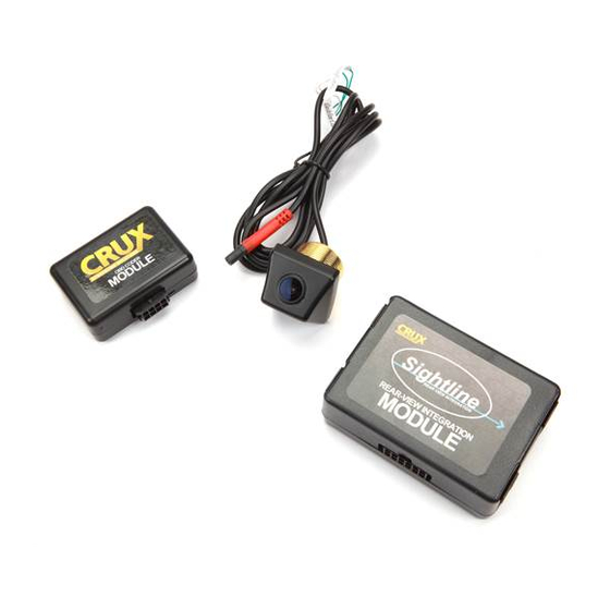
PARTS INCLUDED:
(1) Rear Camera (VW-73)
(1) OBD-73
(1) VW-73 Interface
(1) 15 ft. Extension
(1) VW-73 Harness
(1) Instruction
(1) Power Down Circuit
Camera Specifications:
- Lens Angle 170 Degrees
- Resolution 420 TV Lines
- Min. Illumination 0.2Lux
- Voltage 12v
- Operating Temp: -22˚F - 176˚F
- NTSC/ PAL
- Reference Lines
- Shutter Speed 1/60s - 20us
- Waterproof
- Pixels 656 x 492
PRECAUTIONS:
- Remove the negative side of the battery to avoid any short circuits
during the installation.
- Do not install the interface near any major components or near the
HVAC system. This may cause damage or overheating to the vehicle.
- Do not disconnect the airbag connection behind the radio panel.
:
PRELIMINARY
Please read the entire manual before installing this interface.
TOOLS NEEDED:
- Hex Screw Set
- Drill Gun
INSTALLING THE CAMERA AND CABLE
1. Remove the rear panel.
2. Drill a 5/8 size hole in the location
3. Fish the wires through the drilled hole and through the pass through
into the trunk/cargo area.
4. Remove the factory radio to gain access to the factory connectors.
5. Route the wires towards the radio and make the power and video
connections. For powering up the camera, use the 12v output from
the power down circuit to avoid harm to the camera.
6. Make sure both ground wires have contact with chassis ground.
USING THE POWER DOWN CIRCUIT
The power down circuit is designed to extend the life of the camera.
Note: The green wire is only used to power on the camera and module.
1. Tap the GREEN wire to two red wires, one coming from the camera
and one coming from the module.
(This will provide the camera with a safe guard)
2. Locate the reverse light trigger wire in the vehicle and connect it
to the RED wire. (This will trigger the 12v input)
3. Connect the YELLOW to any available constant source in the car.
4. Connect the BLACK wire to any ground source in the car.
CAMERA CONNECTIONS
i
FACTORY
BAND
NAV
MEDIA
RADIO
MUTE
PHONE
SETUP
COMPATIBLE NAV RADIO
RNS-315 Navigation Radio
INTERFACE
BLACK/GROUND
FROM REVERSE LIGHT
RED/ REVERSE TRIGGER INPUT
YELLOW/ 12V CONSTANT
BLACK/ GROUND
USING THE OBD-73
In order for the vehicle's system to recognize the camera and engage it
when in reverse, the vehicle's system must be coded.
LOCATED NEXT
Reading the LED's color and pattern:
TO THE 8-PIN
Flashing LED
Coding Vehicle
Solid Green LED
Activated
Solid Red LED
Deactivated
Solid Red & Green LED
Error
HOW TO ACTIVATE:
1. Enter the vehicle and close "All the doors" to the vehicle.
2. Turn the key to the "ON" position.
3. Plug the OBD coder to the vehicle, wait for the OBD to code the
car and give you a solid LED status. (See chart above)
4. The radio may flash a few times during this process.
(ETA to code vehicle: 5 seconds) If error: Retry steps.
5. After coding is complete, disconnect OBD from vehicle and store
in a safe place. This OBD is VIN specific, your vehicle's VIN will
stored in its memory. Will not work for any other vehicles.
Remember:
Disconnect OBD
from vehicle but
keep it stored in
OBD CODER
the vehicle.
Testing:
1. Close all doors, turn vehicle to the "ON" position.
2. Engage the reverse gear.
3. Verify the screen switches to rear camera.
4. Done
CONNECTION
26-PIN
(female plug)
12V POWER
12-PIN
(male plug)
RED/ 12V POWER
POWER DOWN
CIRCUIT
GREEN/ 12V OUTPUT (2.7A)
CONNECT TO TURN OFF
GREEN
RED
The parking lines are there to assist you while reversing.
What the lines mean:
Yellow Line: CLEAR
Purple Line: GETTING CLOSE
Red Line: WARNING - VERY CLOSE
To remove the parking lines simply cut the GREEN wire located near
the 4 pin tail connector in the truck.
YELLOW
PURPLE
8-PIN
(male plug)
LED
(indicator)
Rev. 031314
VIDEO
15 ft
(extension)
RED/
BLACK/
GROUND
RED BARREL/
12V CAM POWER
4-PIN BARREL
CONNECT FOR CAMERA
POWER AND SIGNAL
WHITE
(Guide Lines)
BLUE
(Front/ Rear Camera View)
CONNECT FOR FRONT
RED
Advertisement
Table of Contents

Subscribe to Our Youtube Channel
Related Manuals for Crux Sightline RVCVW-73


Summary of Contents for Crux Sightline RVCVW-73
- Page 1 Rev. 031314 REAR-VIEW INTEGRATION INTERFACE W/ CAMERA FOR VOLKSWAGEN 2010-UP VEHICLES RVCVW-73 CAMERA CONNECTIONS We recommend reading this installation guide first before starting any work. Following these instructions from “Start” to” Finish” will ensure a smooth and hassle free installation. We offer telephone support M-F VIDEO 9:00 AM –...
- Page 2 Rev. 020415 REAR-VIEW CAMERA INSTALLATION NOT FOR NAVIGATION RADIOS RVCVW-73/73B NOTE 2012 PASSAT NAVIGATION RADIO RNS-315 Navigation Radio ON THE 2012 PASSAT RADIO THE REAR-VIEW CAMERA WILL TAKE EFFECT AFTER THE CAR GOES TO SLEEP/ POWER DOWN Please do the following steps: 1.
Need help?
Do you have a question about the Sightline RVCVW-73 and is the answer not in the manual?
Questions and answers