
Related Manuals for Renard-Plus TR16


Summary of Contents for Renard-Plus TR16
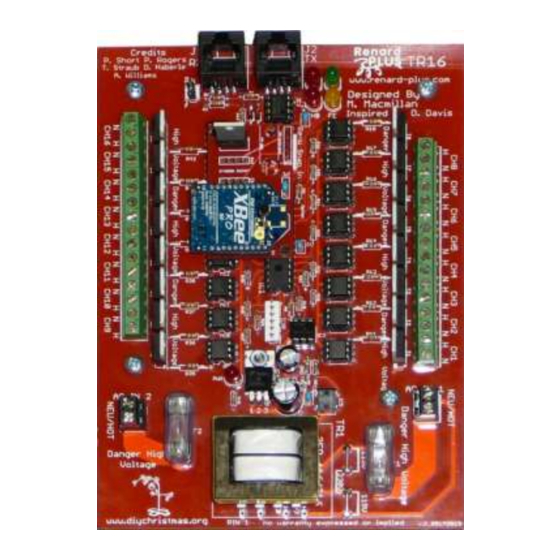
- Page 1 TR16 Controller (Note: Pictured with optional wireless Xbee Snap-in and XBee module) Sep 2017 Board Version 2.00 (v. 2_05172013) Document Rev 1.11...
-
Page 2: Table Of Contents
Table of Contents TABLE OF CONTENTS ..............................2 INTRODUCTION TO RENARD ..........................3 OVERVIEW OF RENARD PLUS TR16 ......................... 4 ASSEMBLY INSTRUCTIONS..........................5 TR16 BOM / P ......................5 ENARD ARTS 3.1.1 Transformer Options ..........................7 3.1.2 TR16 Heatsink ............................7 3.1.3... -
Page 3: Introduction To Renard
Renard Plus Strip Controller. To obtain a specific design, there might be “buy a parts kit and/or blank PCB” offering at a site (such as from www.renard-plus.com), “etch it yourself” files for true DIY, or coop/group buys for kits and PCBs also in forums (like DIYChristmas.org). -
Page 4: Overview Of Renard Plus Tr16
2. Overview of Renard Plus TR16 This guide covers the Renard Plus TR16. This board is designed to take “Renard” serial communications via RS485 from a control computer, and output line level AC to directly power lights/and light strings. The board outputs 16 individually controllable/dimmable channels. The... -
Page 5: Assembly Instructions
“Tools and Parts ID Guide” at: www.renard-plus.com/files/Tools_and_Parts_ID_Guide.pdf 3.1 Renard Plus TR16 BOM / Parts List The following is the Bill Of Material for building the Renard Plus TR16. The link to the Mouser project is: http://www.mouser.com/ProjectManager/ProjectDetail.aspx?AccessID=59f8c86984 Note: If you did not obtain a kit that some lighting vendors offer, Mouser is the most convenient place to order your needed parts. - Page 6 5mm x 20mm Medium Time 5T-VDE-UL-10A-T10A-5x20mm- Delay Fuse 125VAC 10Amp DELAY-ACTING-SLOW-BLOW-10-pcs- /352050825535 534-3527C F1, F2 Fuse Cover (Optional) 838-3FD-416 TR-1 Transformer: (Note: See other Pri.=115/230volts, options) Sec.=8volts 800ma. Renard Plus Page 6 of 27 Renard Plus TR16 Controller www.renard-plus.com Board Version 2.00...
-
Page 7: Transformer Options
115 / 230 12.0 838-3FD-312 115 / 230 838-3FD-316 115 / 230 838-3FS-412 1000 838-3FS-416 838-3FS-420 10.0 838-3FS-424 12.0 838-3FS-312 838-3FS-316 3.1.2 TR16 Heatsink www.renard-plus.com) See template on: Renard Plus Page 7 of 27 Renard Plus TR16 Controller www.renard-plus.com Board Version 2.00... -
Page 8: Tr16 Enclosure
3.1.3 TR16 Enclosure TR16 CG1500 CG1000 (with slight modification to standoffs) Renard Plus Page 8 of 27 Renard Plus TR16 Controller www.renard-plus.com Board Version 2.00... -
Page 9: Parts Assembly
3.2 Parts Assembly The Renard Plus TR16 is a fairly simple device to assemble and test. It is easiest if you follow these instructions, checking off steps as they are performed. This will lead you through the assembly installing components from shortest/smallest to tallest. -
Page 10: Tr16 Assembly Guide
3.3 TR16 Assembly Guide 3.3.1 Select Voltage Setting If you are using a dual voltage transformer from the list of transformer options (typically the 3FD versions), you have the option of strapping the on board power supply to operate from a line voltage of “115”... -
Page 11: Install Resistors
Install the 10k ohm resistor (brown-black- orange) at locations R6. Solder and clip leads. Install the 120 ohm resistor (brown-red-brown) at locations R7. Solder and clip leads. Renard Plus Page 11 of 27 Renard Plus TR16 Controller www.renard-plus.com Board Version 2.00... - Page 12 Install 680 ohm resistors (blue-gray-brown) at locations R19-R34. Solder and clip leads. Install 27k ohm resistors (red-violet-orange) at locations R43, R44. Solder and clip leads. Renard Plus Page 12 of 27 Renard Plus TR16 Controller www.renard-plus.com Board Version 2.00...
-
Page 13: Install By-Pass Caps And Diodes
(band should be toward the center of the board). Renard Plus Page 13 of 27 Renard Plus TR16 Controller www.renard-plus.com Board Version 2.00... -
Page 14: Install Ic Sockets
Install the 6 pin IC sockets at locations M1-M16, and IC3. Solder Note: The two rows of sockets point opposite directions. As shown, the top row faces left, and the bottom row faces right. Renard Plus Page 14 of 27 Renard Plus TR16 Controller www.renard-plus.com Board Version 2.00... -
Page 15: Install Ic Headers
Terminate of the RS485 communications on the last board in a daisy- chained set of boards. Leave un-jumpered for RS232. Install 6 pin header at location ICSP. Solder. Renard Plus Page 15 of 27 Renard Plus TR16 Controller www.renard-plus.com Board Version 2.00... -
Page 16: Install Misc. Parts
+ on it and this corresponds to the plus on the board. This in the lower left hand side as shown. Renard Plus Page 16 of 27 Renard Plus TR16 Controller www.renard-plus.com Board Version 2.00... - Page 17 Install Fuses at F1 and F2. Fuses do NOT get soldered. Note: The fuses can be used to align the fuse clips for soldering as long as you do not overheat them. Renard Plus Page 17 of 27 Renard Plus TR16 Controller www.renard-plus.com Board Version 2.00...
- Page 18 Note: Line up pin 1 marked on the transformer with the pin 1 on the board silkscreen layout. Be careful as it is possible to install the transformer backwards with bad results. Renard Plus Page 18 of 27 Renard Plus TR16 Controller www.renard-plus.com Board Version 2.00...
-
Page 19: Initial Testing
Look for cold solder joints – retouching all solder connections, especially in the power supply area, will often help solve issues like this. When power measures properly, disconnect power and continue assembling. Renard Plus Page 19 of 27 Renard Plus TR16 Controller www.renard-plus.com Board Version 2.00... -
Page 20: Install Ic's
Some MOC parts indicate pin 1 with a dot which goes toward the notch on the silkscreen. Renard Plus Page 20 of 27 Renard Plus TR16 Controller www.renard-plus.com Board Version 2.00... -
Page 21: Picture Of Finished Board
3.3.9 Picture of Finished Board (Note: Pictured with optional Ren Wireless Snap-in and XBee module) Renard Plus Page 21 of 27 Renard Plus TR16 Controller www.renard-plus.com Board Version 2.00... -
Page 22: Final Steps
4.1 Programming the PIC Note: The Renard Plus TR16 does not use the default Renard firmware used on other Renard devices. Make sure you use the Renard Plus version of the code from the Renard-Plus.com... -
Page 23: Jp2 Pic Bypass / Dmx
If you wish to be able to attach to these locations, you can solder a short cut off lead from a resistor or other component to provide you a spot to connect. Renard Plus Page 23 of 27 Renard Plus TR16 Controller www.renard-plus.com Board Version 2.00... -
Page 24: Connecting The Renard To Your Pc
Renard Plus boards as follows. For RS232, TR16 J1 RX pin 4 connects to the serial TX pin (pin 3 of a DE9 female) and J1 pins 5 and 2 and/or 1 connect to serial GND (pin 5 of a DE9 female). For RS485 operation, J1 pins 1 and 2 are GND, pin 4 is Data-, and pin 5 is Data+ on the RS485. -
Page 25: Final Testing
Congratulations, with a successful test, you have completed your build of your Renard Plus controller and are ready for the wonderful world of light animation sequencing! Renard Plus Page 25 of 27 Renard Plus TR16 Controller www.renard-plus.com Board Version 2.00... -
Page 26: Parts Placement Diagram
5. Parts Placement Diagram Renard Plus Page 26 of 27 Renard Plus TR16 Controller www.renard-plus.com Board Version 2.00... -
Page 27: Notes
6. Notes Use this page for YOUR notes about the boards. Renard Plus Page 27 of 27 Renard Plus TR16 Controller www.renard-plus.com Board Version 2.00...
Need help?
Do you have a question about the TR16 and is the answer not in the manual?
Questions and answers