Table of Contents
Advertisement
Quick Links
TR24 Controller
Aug 2016
Board Version 1.00 (v.1_05032013)
Document Rev 1.13
Renard-Plus, Salem, Oregon 97302
© 2011-2015 Renard Plus. All rights reserved.
Published 2016
Printed in United States
Renard-Plus ("Developer") has made every effort to ensure the accuracy of this document. Developer makes no warranties with respect to
this documentation and disclaims any implied warranties of merchantability and fitness for a particular purpose. The information in this
document is subject to change without notice. Developer assumes no responsibility for any errors that may appear in this document.
The information contained herein is the exclusive and confidential property of Renard Plus, except as otherwise indicated.
We wish to also thank the Do It Yourself Community for the inspiration it has given us in the development of this product.
Trademarks: the Renard Plus logo are trademarks of Renard Plus. All other trademarks acknowledged.
Advertisement
Table of Contents

Related Manuals for Renard-Plus TR24


Summary of Contents for Renard-Plus TR24
- Page 1 Printed in United States Renard-Plus (“Developer”) has made every effort to ensure the accuracy of this document. Developer makes no warranties with respect to this documentation and disclaims any implied warranties of merchantability and fitness for a particular purpose. The information in this document is subject to change without notice.
-
Page 2: Table Of Contents
Table of Contents TABLE OF CONTENTS ..............................2 INTRODUCTION TO RENARD ..........................3 OVERVIEW OF RENARD PLUS TR24 ......................... 4 ASSEMBLY INSTRUCTIONS..........................5 TR24 BOM / P ......................5 ENARD ARTS 3.1.1 Transformer Options ..........................6 3.1.2 TR24 Heatsink ............................7 3.1.3... -
Page 3: Introduction To Renard
Renard Plus Strip Controller. To obtain a specific design, there might be “buy a parts kit and/or blank PCB” offering at a site (such as from www.renard-plus.com), “etch it yourself” files for true DIY, or coop/group buys for kits and PCBs also in forums (like DIYChristmas.org). -
Page 4: Overview Of Renard Plus Tr24
2. Overview of Renard Plus TR24 This guide covers the Renard Plus TR24. This board is designed to take “Renard” serial communications via RS485 from a control computer, and output line level AC to directly power lights/and light strings. The board outputs 24 individually controllable/dimmable channels. The... -
Page 5: Assembly Instructions
“Tools and Parts ID Guide” at: www.renard-plus.com/files/Tools_and_Parts_ID_Guide.pdf 3.1 Renard Plus TR24 BOM / Parts List The following is the Bill Of Material for building the Renard Plus TR24. The link to the Mouser project is: http://www.mouser.com/ProjectManager/ProjectDetail.aspx?AccessID=587c062e79... -
Page 6: Transformer Options
115 / 230 10.0 838-3FD-424 115 / 230 12.0 838-3FD-312 115 / 230 838-3FD-316 115 / 230 838-3FS-412 1000 838-3FS-416 838-3FS-420 10.0 838-3FS-424 12.0 838-3FS-312 838-3FS-316 Renard Plus Page 6 of 27 Renard Plus TR24 Controller www.renard-plus.com Board Version 1.00... -
Page 7: Tr24 Heatsink
3.1.2 TR24 Heatsink (Full size Template is available on: www.renard-plus.com) 3.1.3 TR24 Enclosure TR24 CG1500 (CG1000 with stand- off modification) Renard Plus Page 7 of 27 Renard Plus TR24 Controller www.renard-plus.com Board Version 1.00... -
Page 8: Parts Assembly
3.2 Parts Assembly The Renard Plus TR24 is a fairly simple device to assemble and test. It is easiest if you follow these instructions, checking off steps as they are performed. This will lead you through the assembly installing components from shortest/smallest to tallest. -
Page 9: Tr24 Assembly Guide
3.3 TR24 Assembly Guide 3.3.1 Select Voltage Setting Step Instructions TR24 If the controller will be used with 115 volt AC main power, use 2 leftover leads that were clipped and form them to individually jumper the two sets of “115” positions near the transformer. -
Page 10: Install Resistors
R13-R24 and R36-R47. Solder and clip leads. Install 5 of 1K ohm resistors (brown-black-red) at locations R25, R26, R28, R31, and R32. Solder and clip leads. Renard Plus Page 10 of 27 Renard Plus TR24 Controller www.renard-plus.com Board Version 1.00... - Page 11 Install 2 of 330 ohm resistors (orange-orange- brown) at locations R30, R35. Solder and clip leads. Install the 10k ohm resistor (brown-black- orange) at locations R34. Solder and clip leads. Renard Plus Page 11 of 27 Renard Plus TR24 Controller www.renard-plus.com Board Version 1.00...
-
Page 12: Install By-Pass Caps And Diodes
(band should be to the right toward the center of the board). Renard Plus Page 12 of 27 Renard Plus TR24 Controller www.renard-plus.com Board Version 1.00... -
Page 13: Install Ic Sockets
Install the 8 pin IC socket at location IC4. Solder Install 25 of the 6 pin IC sockets at locations M1- M24, and IC1. Solder Renard Plus Page 13 of 27 Renard Plus TR24 Controller www.renard-plus.com Board Version 1.00... -
Page 14: Install Ic Headers
Install 3 pin header at location JP3 / PIC Bypass. Solder Install a shunt jumper on the two left most pins of the header as indicated on the silkscreen. Renard Plus Page 14 of 27 Renard Plus TR24 Controller www.renard-plus.com Board Version 1.00... -
Page 15: Install Misc. Parts
+ on it and this corresponds to the plus on the board. This in the upper right hand corner of IC5 as shown. Renard Plus Page 15 of 27 Renard Plus TR24 Controller www.renard-plus.com Board Version 1.00... - Page 16 “+” symbol. The (+) lead is usually longer than the (-) lead, and the (-) lead is identified by a black or white stripe on the capacitor. Renard Plus Page 16 of 27 Renard Plus TR24 Controller www.renard-plus.com Board Version 1.00...
- Page 17 The thicker line on the silkscreen part location indicates where the tab/flat side of the part should go. If you will be adding an optional Renard Plus Page 17 of 27 Renard Plus TR24 Controller www.renard-plus.com Board Version 1.00...
- Page 18 You are now ready to do some power tests to make sure the board power supply is working properly. Details are in the following section “Initial Testing”. Renard Plus Page 18 of 27 Renard Plus TR24 Controller www.renard-plus.com Board Version 1.00...
-
Page 19: Initial Testing
– retouching all solder connections, especially in the power supply area, will often help solve issues like this. When power measures properly, disconnect power and finish assembling. Renard Plus Page 19 of 27 Renard Plus TR24 Controller www.renard-plus.com Board Version 1.00... -
Page 20: Install Ic's
Some MOC parts indicate pin 1 with a dot which goes toward the notch on the silkscreen. Renard Plus Page 20 of 27 Renard Plus TR24 Controller www.renard-plus.com Board Version 1.00... -
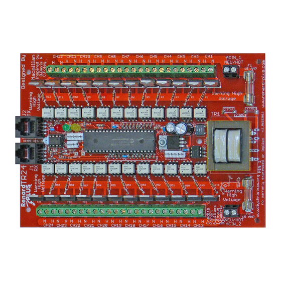
Page 21: Picture Of Finished Board
3.3.9 Picture of Finished Board Renard Plus Page 21 of 27 Renard Plus TR24 Controller www.renard-plus.com Board Version 1.00... -
Page 22: Finishing Steps
Better to touch-up now, rather than having to after it is installed! 4.1 Programming the PIC Note: The Renard Plus TR24 does not use the default Renard firmware used on other Renard devices. Make sure you use the Renard Plus version of the code from the Renard-Plus.com... -
Page 23: Jp3 Pic Bypass / Dmx
If you wish to be able to attach to these locations, you can solder a short cut off lead from a resistor or other component to provide you a spot to connect. Renard Plus Page 23 of 27 Renard Plus TR24 Controller www.renard-plus.com Board Version 1.00... -
Page 24: Connecting The Renard To Your Pc
Renard Plus boards as follows: For RS232, TR24 J1 RX pin 4 connects to the serial TX pin (pin 3 of a DE9 female) and J1 pins 5 and 2 and/or 1 connect to serial GND (pin 5 of a DE9 female). For RS485 operation, J1 pins 1 and 2 are GND, pin 4 is Data-, and pin 5 is Data+ on the RS485. -
Page 25: Computer Setup
Congratulations, with a successful test, you have completed your build of your Renard Plus controller and are ready for the wonderful world of light animation sequencing! Renard Plus Page 25 of 27 Renard Plus TR24 Controller www.renard-plus.com Board Version 1.00... -
Page 26: Parts Placement Diagram
5. Parts Placement Diagram Renard Plus Page 26 of 27 Renard Plus TR24 Controller www.renard-plus.com Board Version 1.00... -
Page 27: Notes
6. Notes Use this page for YOUR notes about the boards. Renard Plus Page 27 of 27 Renard Plus TR24 Controller www.renard-plus.com Board Version 1.00...
Need help?
Do you have a question about the TR24 and is the answer not in the manual?
Questions and answers