
Related Manuals for Weldcote MIG STRIKER 200


Summary of Contents for Weldcote MIG STRIKER 200
- Page 1 Quick Guide Manual STRIKER MULTI-PROCESS (STICK/MIG/TIG) WELDING MACHINE FOR STEEL, STAINLESS STEEL AND ALUMINIUM...
-
Page 2: Safety Warning
DC WELDING INvERTER FOR MANUAL ARC WELDING SAFETY WARNING On the process of welding or cutting, there will be possibility of injury, so please take protection into consideration during operation. For more details please review the Operator Safety Guide, which complies with the preventive requirements of the manufacturer. -
Page 3: Work Area
1.1 EqUIPMENT • Repair and maintenance to be performed by authorized personnel only. • The welding machine is to be maintained in good operational conditions (dry and clean). • The welding machine is not to be positioned in a closed space or next to a wall while welding in order to avoid problems with venting. -
Page 4: General Information
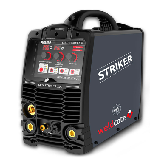
2.0 GENERAL INFORMATION 2.1 DESCRIPTION 1. Digital current display 2. Welding current adjustment 3. Digital voltage display / wire speed 4. Dial for adjusting voltage/down slope/arc force 5. POWER ON indication light - is on when the welding machine is connected to a live socket and is on. -
Page 6: Special Features
2.2 PARAMETERS PARAMETERS MIG STRIKER 200 STICK 1~120±10% Input voltage (A) 1~230±10% 25.5 Rated Input Current (A) 26.1 20.3 30.2 Rated Input Power (KW) 10~140 10~140 10~110 Welding Current Range (A) 10~200 10~200 10~200 Welding voltage (v) 10~26 No-load voltage (v) -
Page 7: Installation
3.0 INSTALLATION 3.1 MAIN CONNECTIONS Before connecting to the power grid, verify the supply voltage is in range of the machine parameters. • The power cable plug is to be connected to standard approved socket, with the proper protections. • The ground line (green & yellow) is to be connected to the grounding pin. 3.2 MIG WELDING OPERATION 3.2.1 MOUNTING THE WIRE SPOOL The machine is designed to use 11lb spools (8"... -
Page 8: Setup For Spool Gun Mig (Gmaw) Welding With Gas Shielded Mig Wire
3.2.2 SETUP FOR MIG-GUN MIG (GMAW) WELDING WITH GAS SHIELDED MIG WIRE A. Select MIG mode with the process selection control (11). B. In most cases the MIG polarity selector (22) is to be connected to the negative position (-), as shown in the sketch. -
Page 9: Argon Arc Welding Operation
3.2.4 SETUP FOR WELDING WITH SELF SHIELDED MIG WIRE A. Follow the above steps according to the type of welding gun used (3.2.1 or 3.2.2), with the following differences is steps B and E: B. In most cases the MIG polarity selector (22) is to be connected to the negative "-", and earth cable connects to "+"... -
Page 10: Setup For Stick (Mma) Welding
current (5A) t2~t3: During the whole welding process, the gun switch is pressed and held without releasing; t3: Release the gun switch, the output current slopes down; t3~t4: The output current slopes down to minimum current (5A), stop arc; adjustment range of down slope time: 0~5S;... - Page 11 4.0 WELDING ACCESSORIES: CONNECTION AND APPLICATION 4.1 WORK LEAD WITH WORK CLAMP The work clamp is to be connected directly to the work piece or the work table with good electrical continuity to the work piece. Careful! Avoid using coated or non-metallic, non-conducting work-benches. 4.2 WELDING LEAD WITH ELECTRODE HOLDER This cable has a special handle that holds the exposed part of the coated electrode.
- Page 12 5.0 GRAPHIC SyMbOLS AND INDICATIONS U1: Rated AV input voltage (with tolerance ±10%). I1max: Rated maximum input current. I1eff: Maximum effective input current. X: duty cycle. The ratio of given duration time/the full-cycle time. Note1: This ratio shall be within 0~1, and can be indicated by percentage. Note2: In this standard, the full-cycle time is 10min.
-
Page 13: Operation Environment
6.0 OPERATION ENvIRONMENT • Height above sea level is below 1000m. • Operation temperature range: -10°C+40°C / 14°F~104°F. • Relative humidity is below 90% (200°C/68°F), relative humidity is below 50% (400°C/104°F). • The inclination of the power source does not exceed 10°. •... - Page 14 PFC TECHNOLOGY Reduces energy consumption up to 50% considering the model of conventional type welding machine and enables usage of energy in high efficiency and high quality. Supply Voltage and Current over time comparison (under steady load): Large Small Energy Energy Loss Loss...
-
Page 15: Warranty Card
WARRANTy CARD year warranty Customer Name: Serial Number: Address: Email: Model Number: Tel Number: Dealers Name: Date Of Purchase: Dealers Signature And Stamp: WARRANTY TERMS: 1. The warranty is valid for three years for any manufacturing defect. 2. This warranty is canceled if this certificate is not sent immediately upon purchase with tax invoice attached. - Page 16 The warranty is valid under the following conditions: • Stamped and signed by the seller. • The warranty certificate arrived at the WELDCOTE offices within 14 days of the purchase, together with an invoice. Weldcote Metals 842 Oak Grove Road, Kings Mountain, NC 28086 USA.
Need help?
Do you have a question about the MIG STRIKER 200 and is the answer not in the manual?
Questions and answers