Table of Contents
Advertisement
Quick Links
Advertisement
Table of Contents

Subscribe to Our Youtube Channel
Related Manuals for Keller HP Series

Summary of Contents for Keller HP Series
- Page 1 KELLER May 2006...
- Page 2 ncluded In elIvery ncluded In elIvery ressure alIbrator ressure alIbrator tandard ersIon ersIon – 1 Calibrator – 1 Calibrator – 1 Carrying Case – 1 Carrying Case – 1 Test-Unit Adapter G 1/4” / G 1/2” – 1 Test-Unit Adapter G 1/4” / G 1/2” –...
-
Page 3: Table Of Contents
Ist oF ontents Executing Storage of Measured Values Outline Drawing – r -Mode General Description Measuring the Linearity* Operating the Calibrator – l -Mode* – Turn-On – Connecting Test-Units Calculating the Linearity* – l -Mode* – Executing Functions and Commands –... -
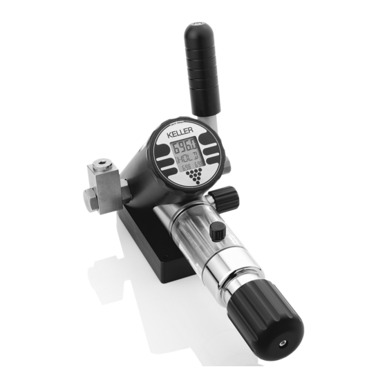
Page 4: Outline Drawing
Oil-Level 12 13 KELLER Connector for RS 232 Output 11a) Outlet Pressure Port (G 1/4”, female) (Standard Version) with Hexagon Plug (200 bar and 350 bar 1b)* Connector for RS 232 Output Calibrator with Overpressure Valve) (Full-Version) 11b) Outlet Pressure Port (G 1/4”, female) -
Page 5: General Description
eneral escrIPtIon The calibrator combines a number of functions The calibrator has an internal memory for recor- and performance features. Please take your ding data. It can either be filled with the linea time reading this manual thoroughly prior to rity measurements (function l )*, the switching setting the calibrator into operation. -
Page 6: Operating The Calibrator
PeratIng alIbrator ressure eneratIon The calibrator is turned on by pressing the func- Attention: To avoid an overpressure within the tion key once. oil chamber, the oil refill screw (9) must be open when operating the calibrator! onnectIng nIts Adapter: Generate pressure with the priming pump (12) Included in the delivery of the calibrator are up to approx. -
Page 7: Description Of The Functions
escrIPtIon oF tHe unctIons For a better understanding, the operating ele- In M -Mode: To reset peak- and ments are described again: trough-pressure. (F-Key) To turn off the instrument. unctIon The function key on the front of the instrument, marked by a pointed triangle, serves to operate To display the actual pressure the instrument. -
Page 8: Measuring Mode
The M -Mode is the standard mode of the ca- Actual librator. In this mode, the calibrator shows on Pressure the upper display the actual pressure generated. The smaller displays below indicate the peak- Peak Trough and trough values. The measured values on the smaller displays always appear with a reduced resolution. -
Page 9: Temporarily Setting New Zero Reference
The t -Mode serves to set a temporary zero The u -Mode allows the selection of one of reference. Unlike to the Z -Mode, this new four pressure units. zero reference will not remain after the instru- Activate u ment has been turned off. Activate t Value to be set to zero... -
Page 10: Preparing The Leak-Test
The l -Mode serves to measure a pressure change over a programmable time. The unit to be tested has to be connected to the calibrator. Setting the Test Time: Second digit is flashing, Activate l encreases digit… With s to next digit. When the test time is set, activate P . -
Page 11: Executing The Leak-Test
Start of the l -Test: After the test, the measured values are frozen in. Activate P to return to the P -Mode from After setting the test time, the display is in the the e display. -Mode: A new test can be started as follows (also when measurements are running). -
Page 12: P St -Mode
ersion only This mode allows the testing of mechanical and electronic switches. The display always indi- cates the switch status and the switch pressure points. The actual status (o ) and the lose switch pressure are being displayed with each change of status in the pressure switch. - Page 13 ersion only Note: The test measurements can be started in each position of the connected pressure switch. The first point is automatically written into the In the s mode, a new small right display (Low) if the measurement switch can be connected started at high pressure and the pressure switch without influence on status or recording.
-
Page 14: Preparing Storage Of Measured Values
In the r - (or Record) Mode, the measured values can be stored. The number of measure- ments and the interval (in minutes and seconds) are programmable. Subsequently, one storage cycle over the num- First digit is flashing; ber of measurements is called a “recording”. increases digit. -
Page 15: Executing Storage Of Measured Values
Start of the Recordings: The display e indicates the end of the recor- ding. Activate P to return to the P -Mode After the adjustment of the storage parameters, from the e display. the display is in the P -Mode: At any time, a record can prematurely be termi- nated by activating r In the r -Mode you may also display the tem-... -
Page 16: In -Mode
ersion only The linearity mode allows the determination of The Linearity Test: the linearity error of a test-unit. The linearity is calculated as terminal linearity, that means, the Activate l line is set between the first and the last measu- ring point. Actual Pressure The linearity error is indicated as a percen- Number of tage of the span between the first and the last measuring point... -
Page 17: Calculating The Linearity
ersion only Calculating the Linearity: From this position, the linearity of all other measuring points can be called upon: After registration of the measuring points, the calculation of the linearity is initiated with the Pressure at point 3 command C After the calculation, the pressure and measu- ring point with the highest linearity error are shown: Activate E... -
Page 18: Adjusting The Display-Resolution
-Mode: -Mode: The activation of r reduces the resolution by Ambient pressure changes, dependency of posi- factor 10 or sets the display back to the original tion or the influence of temperature can result in resolution. zero shifts. These shifts can be permanently corrected as follows. Activate Z Activate R Actual Zero... -
Page 19: Data Transfer To Pc
ransFer to ransFer to llocatIon (only with Logger-Option) After each recording (l *, P *, r ), the calib- rator writes the status of the calibrator’s time In order to transfer the data from the calibrator meter into the memory. When transferring, the into a PC, a special cable (K101) and a special absolute time-axis is calculated from the time software is required. -
Page 20: Maintenance
An external supply can be plugged to connec- tion (13), e.g. 13 V for KELLER transmitters. 3,6 v b The adapter plug, included in the delivery, auto- attery The calibrator will not indicate a battery low. If matically interrupts the 9 V battery supply. -
Page 21: Operating Guide/Functions
PeratIng uIde unctIons FUNCTIONS The calibrator is turned on by pressing the func- tion key (7) once. Display of pressure, max. and min. pressure. e resets peak- and trough values. With test-unit connected*: Display of actual unctIons and ommands The functions and commands are activated pressure, transmitter signal and temperature. -
Page 22: Technical Data
ecHnIcal Total Accuracy of displayed Pressure ±0,1% FS (Full Scale), from 0…50 °C Total Accuracy of displayed Test Unit Signal ±0,1% FS ±1 Digit Resolution of Display 200 bar Calibrator 10 mbar 350 bar Calibrator 100 mbar 700 bar Calibrator 100 mbar Overpressure FS + 10%... -
Page 23: Declaration Of Conformity
As criteria for the electromagnetic compatibility, the following norms are applied: EN - 61000 - 6 - 1 EN - 61000 - 6 - 3 This declaration is given for the manufacturer Keller AG für Druckmesstechnik St. Gallerstrasse 119 CH - 8404 Winterthur in full responsibility by... - Page 24 www.keller-druck.com...
Need help?
Do you have a question about the HP Series and is the answer not in the manual?
Questions and answers