Table of Contents
Advertisement
Quick Links
Advertisement
Table of Contents

Subscribe to Our Youtube Channel
Related Manuals for Power Probe Tek Power Probe III S

Summary of Contents for Power Probe Tek Power Probe III S
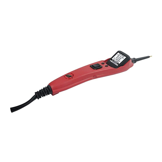
- Page 2 INTRODUCTION Thank you for purchasing the NEW Power Probe IIIS (PP3S). The PP3S is our most revolutionary circuit tester to date. The PP3S literally speeds you through the diagnosing of 12 to 24 volt auto- motive electrical systems. After connecting the PP3S’s clips to the vehicle’s battery, the automo- tive technician can determine at a glance, the voltage level and the polarity of a circuit with out running for a voltmeter or reconnecting hook-up clips from one battery pole to the other.
-
Page 3: Table Of Contents
Table of Contents Hook-up and quick self-test ......................3 Turning the Audio Tone On & Off ..................... 3 Circuit Breaker ..........................4 Voltage & Polarity testing ....................... 5 Continuity testing .......................... 5 Activating components out of vehicle’s electrical system ..............6 Testing trailer lights and connections.................... -
Page 4: Hook-Up And Quick Self-Test
Hook-Up Unroll the Power Probe cable. Connect the battery hook-up clip to the POSITIVE terminal of the vehicle’s battery. Connect the BLACK battery hook-up clip to the NEGATIVE terminal of the vehicle’s bat- tery. When the PP3S is first connected to a battery (power source), it will sound a quick start up tone and then go into Voltmeter Mode (See Mode #1 on page 10) and the 2 bright white LEDs (dual headlights) will be on to illuminate the test area of the probe tip. -
Page 5: Circuit Breaker
Circuit Breaker In Voltmeter Mode (Mode #1) with the circuit breaker tripped, the display will show “Circuit Breaker Tripped”(see page 11-12 for detail) All other functions of the PP3S are still active. This means that you can still probe a circuit and observe the voltage reading. When the circuit breaker is tripped, the PP3S will NOT be able to conduct battery current to the tip even when the power switch is pressed. -
Page 6: Continuity Testing
Continuity Testing While the PP3S is in Voltmeter Mode, and by using the Power Probe tip in connection with chassis ground or the auxiliary ground lead, continuity can be tested on wires and components attached or disconnected from the vehicle’s electrical system. The PP3S indicates continuity using 2 resistance levels. -
Page 7: Activating Components Out Of Vehicle's Electrical System
Activating Components In Your Hand While the PP3S is in Voltmeter Mode and by using the Power Probe tip in connection with the auxiliary ground lead, components can be activated right in your hand, thereby testing their function. Connect the negative auxiliary clip to the negative terminal or ground side of the component being tested. -
Page 8: Testing Trailer Lights And Connections
Testing Trailer Lights & Connections 1. Connect the PP3S to a good battery. 2. Clip the auxiliary ground clip to the trailer ground. 3. Probe the contacts at the jack and then apply voltage to them. This lets you check the function and orientation of the connector and trailer lights. -
Page 9: Activating Electrical Components In The Vehicle
Activating Components On Vehicle To activate components with positive (+) voltage: Contact the probe tip to the positive terminal of the component, the green negative sign “-” LED should light. Indicating continuity to ground. While observ- ing the green indicator, quickly depress and release the power switch forward (+). If the green indicator went out and the red positive... -
Page 10: Activating Electrical Components With Ground
Activating Components w/Ground Contact the probe tip to the negative terminal of the component, the LED indicator should light RED. While observing red positive sign “+” LED, quickly depress and release the power switch rearward (-). If the red indicator went out and the green negative sign (-) came on you may proceed with further activa- tion. -
Page 11: Checking For Bad Ground Contacts
Checking For Bad Grounds Probe the suspected ground wire or contact with the probe tip. Observe the green negative sign “-” LED. Depress the power switch forward then release. If the green negative sign “-” LED went out and the positive sign “+”... -
Page 12: Modes 1, 2, 3
Modes The Power Probe IIIS has been designed to work the same as the previous Power Probe circuit testers. Using the ad- vanced features and modes is optional. However, understanding them will expand your diagnosing capabilities. The LCD display indicates voltage levels of the circuit along with an identifying symbol showing you what mode it is in. The additional features contain 5 new modes which give you specific information about how the circuit is reacting. -
Page 13: Modes 4, 5, Chart
Mode #4 Min Peak Mode: The Min Peak Mode monitors a positive circuit and displays the lowest voltage that it has dropped to. To do this: Place the PP3S into Min Peak Mode by selecting MIN PEAK from the menu. The display will show 00.0 volts if the probe tip is not connected to any voltage. -
Page 14: Specifications
Power Probe III S Specifications Storage temperature/humidity: -20 to 70℃, 70% RH max Operating temperature/humidity: -10 to 50℃, 70% RH max Pollution degree: 2 DC Voltage ....0 to +70 Volts +1 digit P-P Voltage ....0 to +70 Volts... -
Page 15: Replacement Parts
The Power Probe 3S is engineered for years of reliable service. Some components can wear out over time with heavy use. Replacement parts can be obtained from your tool dealer or by contacting Power Probe Tek’s Technical Support department at 1-800-655-3585 or email to support@pp-tek.com... - Page 16 s u p p o r t @ p o w e r p r o b e t e k . c o m...
Need help?
Do you have a question about the Power Probe III S and is the answer not in the manual?
Questions and answers