
Related Manuals for Power Probe Tek PRO SERIES THE MAESTRO

Summary of Contents for Power Probe Tek PRO SERIES THE MAESTRO
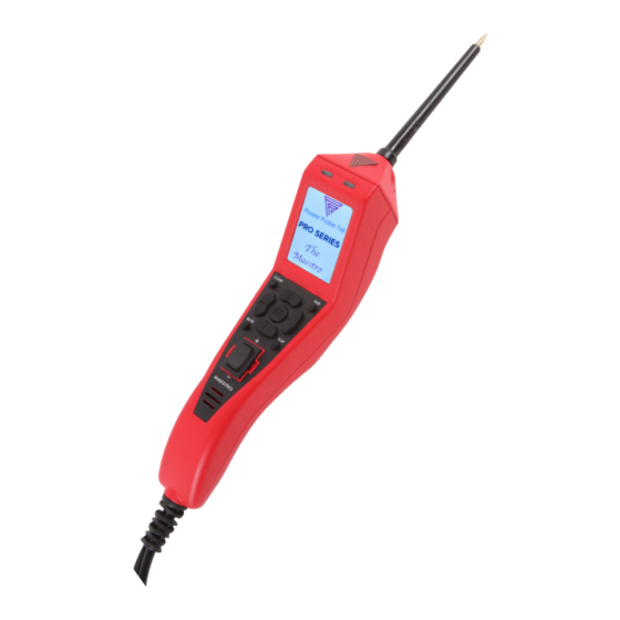
- Page 1 PRO SERIES THE MAESTRO™ Conforms to UL STD. 61010-1, 61010-2-030, and 61010-031 Certified to CSA STD. C22.2 NO. 61010-1, 61010-2-030 and 61010-031 WWW.POWERPROBETEK.COM...
-
Page 2: Table Of Contents
• Frequency Measurement ........... 19 • Trace Mode ................20 Advanced Testing Operations • Fuel Injector Mode ............. 23 • Power Probe TEK Pro Series APP..........25 • Pairing ..................27 Tool Repair Operations ..............28 Specifications ..................29 Warranty ....................30... -
Page 3: Introduction
INTRODUCTION Thank you for purchasing the Pro Series Maestro™ Diagnostic Electronic Circuit and Component Tester. This is the first of our Pro Series line of tools made for Professionals. With powerful multimeter functions, ad- vanced diagnostic modes, easy to read color LCD display, and a new rugged dust and water resistant housing. -
Page 4: Safety
• Power Probe TEK shall not be liable for damage to vehicles or components caused by misuse. • Power Probe TEK shall not be held liable for any harm caused by unintentional or intential misuse of our products or tools. -
Page 5: Appearance And Controls
APPEARANCE AND CONTROLS Removeable Probe Tip uses standard 4mm banana type connector enabling use of different probes, leads, or extensions. LED, Green (-) Will light indicating a path to ground. More than 10 Ω resistance and/or more than 0.5 volts on a ground circuit, the Green LED will not illuminate. - Page 6 APPEARANCE AND CONTROLS Rear Cover SERIAL NUMBER CIRCUIT BREAKER (RE- PLACEABLE) PART # PPTK0030 USB CONNECTOR 5 X 20mm 20A FAST BLOW FUSE; PART # PPTK0042 WWW.POWERPROBETEK.COM...
-
Page 7: Ez Learning
INTRODUCTION TO EZ LEARNING EZ Learning Mode will guide you through a step by step fa- miliarization of the Maestro™, showing you how to operate the tool and how the probe responds in certain testing conditions. From the Main Menu select the EZ Learning icon. EZ Learning will take you through a step by step process. -
Page 8: Guided Diagnostics
INTRODUCTION TO GUIDED DIAGNOSTICS Guided Diagnostics Mode will help guide you through specific ve- hicle or components test and let you know if readings obtained are acceptable to outside of the normal readings. From the Main Menu, click on The Guided Diagnostics icon. With Guided Diagnostics, you can have a better understanding of the ba- sic testing steps in electrical diagnosis. -
Page 9: Start Up
START-UP Operation Source Voltage Maestro™ is designed to connect to and is powered by 12 to 24 VDC electrical systems. It comes supplied with a 23 ft. heavy duty power cable and a Y-connector with 2 battery clips. Connecting To The Vehicle’s Battery 4”... -
Page 10: Main Menu
MAIN MENU Maestro™ provides a more updated user interface and combines it with an App that expands the tools capability and access to knowledge. To access the features of this tool, there are new buttons provided that are intuitive and simple to understand. All buttons only have one function marked, no extended pressing or double pressing is required. -
Page 11: Mode Navigation
MODE NAVIGATION Maestro™ has 5 different test modes available inside Multi Meter Mode and 1 stand alone mode: 1. VDC - For DC voltage measurements. This is the default mode on startup. Max. 200 VDC 2. OHM - For resistance readings. All readings are current loaded so wire issues will cause readings to appear different than other meters. -
Page 12: Dc Voltage In Vdc Mode
DC VOLTAGE MEASUREMENT IN VDC MODE In this mode, you will supply battery power or battery ground to the tip when pressing the rocker switch VDC - VDC mode is for testing DC (direct current) voltages. Voltage testing is as easy as contacting the probe tip to a circuit and reading the display. -
Page 13: Activating Components
ACTIVATING COMPONENTS IN VDC MODE Activating Electrical Components in VDC Mode is one of the Maestro™ main features that makes the very useful in test- ing. Being able to apply battery power or ground right to the probe tip gives you the ability to activate and dynamically test electrical components such as lights, mo- tors, and solenoids. -
Page 14: Resistance Testing On Ohm Mode
RESISTANCE TESTING IN OHMMETER OHMMETER is used to check resistance on static circuits or voltage by simply probing the connection of the circuit being tested. OHMMETER is used like a standard Ohmmeter and measures total circuit resistance from the source battery accurately with the Aux. Ground lead whether there is voltage feeds on the Maestro™... -
Page 15: Power Feed Test
POWER FEED TESTING FEED TEST - Power Feed Test is used to identify voltage drops on active circuits by probing one connection of the circuit being tested. PFT displays both Battery and Tip voltage simultaneously for easy voltage drop testing. While testing, use the Aux. - Page 16 OHM TESTING AND POWER FEED To test, first disconnect the device or load being operated from the circuit, then contact the probe tip to the circuit being tested. Disconnecting the component from the circuits prevents it from affecting and altering the resistance reading.
-
Page 17: Ac Voltage Measurement (Rms)
AC VOLTAGE MEASUREMENT (RMS) AC RMS Mode is for measuring AC (al- ternating current ) voltages and can be used on any AC voltage or pulsed waveform signal where an RMS average voltage measure- ment is required. Contact the probe tip to the circuit and it will display an RMS averaged AC voltage reading in the main display area while also displaying RMS Min/Max AC voltages on the top and... -
Page 18: Ac Voltage Measurement (P To P)
AC VOLTAGE MEASUREMENT (P-P) P-P Mode can be used on any AC voltage signal where a Peak to Peak (P-P) voltage measurement is required. P-P stands for Peak to Peak AC voltage. Where AC RMS displays an average AC voltage, P-P does not average the read- ing but displays the total voltage differ- ence from the lowest to highest voltage extreme on an AC signal. -
Page 19: Frequency Measurement
FREQUENCY MEASUREMENT FRQ CTR - Frequency Counter mode is used for measuring the frequency of an alternating voltage signal. Contact the probe tip to the circuit and it will display the frequency in Hertz (cycles per second) and Duty Cycle on the top and also displaying the + Pulse Width and - Pulse Width in milliseconds on the bottom. -
Page 20: Trace Mode
TRACE MODE The Maestro™ has a new feature called Trace Mode. In Trace Mode, you can view the data as a wave form. Trace Mode can be found in VDC, VAC, Frequency, and Injector Modes. Each mode displays relevant information tailored for automotive testing. - Page 21 TRACE MODE (CONT.) For instance, if 12V is on the tip with no fluctuation, it will display as a straight line at the top of the active trace area (ATA). If 50V is on the tip, it will also display at the top of the ATA as a flat line. You will see that the voltage value of the trace is displayed under TIP.
- Page 22 TRACE MODE (CONT.) Trace Mode In VAC VAC Trace Mode works differently. VAC Trace Mode will provide the same information as in normal AC Mode while viewing the signal including the average RMS AC and the highest RMS AC and lowest RMS AC both cap- tured in the MIN and MAX.
-
Page 23: Fuel Injector Mode
FUEL INJECTOR MODE FUEL INJ - Fuel Injector Mode is specifically set up for fast and easy injector circuit diagnosis. One quick connection to the circuit and the Maestro™ will display all the needed fuel injector testing information that would normally require using a lab-scope. Below is an example of a typical fuel injector voltage waveform on a lab scope. - Page 24 FUEL INJECTOR MODE • Select INJECTOR from the Menu. • Back-probe on the negative side of the in- jector either at the injector or at the PCM. • These four data points represent the cor- responding waveform points. • When the engine is running (or cranking) the tool’s red and green indicator LEDs will blink to indicate a good signal from the ECM/PCM.
-
Page 25: Power Probe Tek Pro Series App
THE PRO SERIES APP The Maestro™ has a new feature designed to help the mechan- ic in the shop by providing resources and additional diagnostic functions. The Pro Series app is a diagnostic app developed for both iOS and Android that can quickly provide you with up to date problem solving information and news, unique special tool applets and the ability to log, i.e., replay and share diagnostic data occuring on the tip. - Page 26 When you plug into the Pro Series App, you are plugging into the future of automotive diagnostics. Visit iTunes or Google Play to donwload the Power Probe TEK Pro Series App for free and begin getting more out of your Power Probe TEK Tools.
-
Page 27: Pairing
With the tool powered on, open your Pro Series App. You will see a selection to Pair Device. This will work with all Power Probe Tek Tools that use the wireless communication. Press the Pair button on the app, it will prompt you to begin the pairing process. -
Page 28: Tool Repair Operations
ROCKER SWITCH REPLACEMENT Maestro™ Rocker Switch is used constantly and arcing can occur across the switch contacts and eventually the switch can wear out. Maestro™ also has an Automatic Resetting 8 Amp Thermal Circuit Breaker and like the Rocker Switch, the Circuit Breaker can also wear out over time. -
Page 29: Specifications
PRODUCT SPECIFICATIONS Min Operating Voltage 9 VDC Max Operating Voltage 30 VDC Max Tip Voltage 450 Volts Probe Tip Resistance to Ground 350 K Ohms Computer Safe 0.1mA floating tip Voltage Measurement -100 to 200 VDC/VAC Voltage Resolution -99.99 to 99.9 V - 0.01V (10mV) GIitch Capture >380µS Min Pulse Width Power Feed Test... -
Page 30: Warranty
POWER PROBE TEK WARRANTY Power Probe TEK Products undergo a strict quality control in- spection for workmanship, function, and safety before leaving the factory. From the date of purchase, we will warranty/repair Power Probe TEK products for one (1) year against defects in parts and workmanship. - Page 31 Power Probe TEK, LLC. 760 Challenger St. Brea, CA 92821 toll free 800.655.3585 local 714.990.9443 fax 714.990.9478 Power Probe The Next Generation of Diagnostics...
Need help?
Do you have a question about the PRO SERIES THE MAESTRO and is the answer not in the manual?
Questions and answers