Table of Contents

Related Manuals for cias PYTHAGORAS2 Series

Summary of Contents for cias PYTHAGORAS2 Series
- Page 1 PYTHAGORAS2 Barriera Multi-tecnologia Microonde e infrarosso per protezioni esterne Manuale di Installazione/ Multi-technology Barrier Microwave and Infrared Installation Manual Edizione / Edition 1.1...
-
Page 2: Table Of Contents
CIAS Elettronica S.r.l. Ed. 1.1 INDICE DESCRIZIONE ..................................... 3 1.1 D ......................................3 ESCRIZIONE INSTALLAZIONE ....................................4 2.1 M ..................................4 ONTAGGIO DELLE UNITÀ 2.2 N ....................................6 UMERO DI RATTE ’I 2.3 A ................................ 7 VVERTENZE PER L NSTALLAZIONE 2.4 C... - Page 3 CIAS Elettronica S.r.l. Ed. 1.1 INDEX DESCRIPTION ....................................37 1.1 D ......................................37 ESCRIPTION INSTALLATION ....................................38 2.1 M ..................................38 OUNTING OF THE 2.2 N ....................................40 UMBER OF ONES 2.3 I ..................................41 NSTALLATION DVICE 2.4 G ....................................
-
Page 4: Descrizione
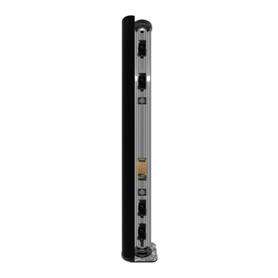
CIAS Elettronica S.r.l. Ed. 1.1 1 DESCRIZIONE 1.1 Descrizione PYTHAGORAS2 è una barriera multi tecnologia per protezioni volumetriche perimetrali esterne. La barriera è in grado di rilevare la presenza di un corpo che si muove all’interno di un campo sensibile instauratosi tra il Trasmettitore (TX) e il Ricevitore (RX). -
Page 5: Installazione
CIAS Elettronica S.r.l. Ed. 1.1 2 INSTALLAZIONE 2.1 Montaggio delle unità Per il montaggio delle due unità (TX e RX) fissare la base di sostegno a terra. Aprire ogni singola colonna partendo dal coperchio superiore. Rimuovere le viti con l’aiuto di un cacciavite. - Page 6 CIAS Elettronica S.r.l. Ed. 1.1 Nella parte superiore di ciascuna colonna sono presenti due interruttori (tamper) in serie. Quello laterale segnala la rimozione del coperchio superiore. Quello centrale segnala invece la pressione sul coperchio ed è quindi indicato per rivelare tentativi di scavalcamento.
-
Page 7: Numero Di Tratte
CIAS Elettronica S.r.l. Ed. 1.1 2.2 Numero di Tratte Dovendo progettare la protezione con barriere volumetriche di un perimetro chiuso, oltre alle normali considerazioni di suddivisione del perimetro in un certo numero di tratte che tengano conto delle necessità gestionali dell'intero impianto, occorre ricordare che è sempre preferibile installare un numero di tratte pari. -
Page 8: Avvertenze Per L'installazione
CIAS Elettronica S.r.l. Ed. 1.1 2.3 Avvertenze per l’Installazione Per una corretta installazione delle barriere infrarosso, è necessario attenersi alle seguenti regole: Non posizionare i ricevitori in modo tale che la luce solare, diretta o riflessa, possa raggiungerli. Infatti se la luce solare, colpisse direttamente o per riflessione i ricevitori, potrebbero manifestarsi falsi allarmi. -
Page 9: Ampiezza Dei Fasci Sensibili Amw
CIAS Elettronica S.r.l. Ed. 1.1 2.6 Ampiezza dei Fasci Sensibili a MW L'ampiezza del Campo Sensibile è in funzione dalla regolazione di sensibilità impostata. Le figure seguenti ci forniscono la dimensione a metà tratta del Fascio Sensibile, in funzione della lunghezza della tratta, nel caso di sensibilità... -
Page 10: Collegamenti
CIAS Elettronica S.r.l. Ed. 1.1 3 COLLEGAMENTI 3.1 Morsettiere, connettori e Funzionalità dei Circuiti 3.1.1 Circuito di controllo Trasmettitore TERMINAZIONE DI LINEA RS 485 JP2 LED GUASTO TAMPER SYNC Figura 5 Disposizione topografica dei componenti nel circuito di controllo Tx... - Page 11 CIAS Elettronica S.r.l. Ed. 1.1 CONNETTORE J2 TRASMETTITORE Simbolo Funzione Massa per Oscillatore a MW Collegamento per Oscillatore a MW Massa per Oscillatore a MW CONNETTORE J3 TRASMETTITORE Simbolo Funzione 1-2-3-5-8-9-10-11- N.C. Non Connesso 14-15 Massa +13,8 Tensione di Alimentazione (13,8 V )
-
Page 12: Circuito Di Controllo Ricevitore
CIAS Elettronica S.r.l. Ed. 1.1 3.1.2 Circuito di controllo Ricevitore B Z 1 J p 2 O F F S W 2 S W 3 S W 4 S W 5 S W 1 O F F J p 1... - Page 13 CIAS Elettronica S.r.l. Ed. 1.1 CONNETTORE J2 RICEVITORE Simbolo Funzione Massa per Rivelatore a Microonde Collegamento per Rivelatore a Microonde (Detector) Massa per Rivelatore a Microonde CONNETTORE J3 RICEVITORE Simbolo Funzione 1-2-3-5-8-10-11-13- N.C. Non Connesso 15-16 Massa +13,8 Tensione di Alimentazione (13,8 V )
-
Page 14: Circuito Tx E Rx Ir
CIAS Elettronica S.r.l. Ed. 1.1 SELETTORE DI FUNZIONI SUL RICEVITORE Simbolo Funzione Posizione 1 = Allineamento Barriera MW Posizione 2 = Acquisizione parametri Barriera MW (Canale, Valore di Campo, Acquisizione Soglie di Sensibilità e Mascheramento, Indicazione della Qualità dell’Allineamento) Posizione 3 = Walk Test Barriera MW, acquisizione Soglie di sensibilità... -
Page 15: Circuito Di Interfaccia Trasmettitore
CIAS Elettronica S.r.l. Ed. 1.1 3.1.4 Circuito di Interfaccia Trasmettitore M S 1 M S 5 M S 2 + 1 3,8 V D IS Q D Z D IR H ig h P o w er G N D... -
Page 16: Circuito Di Interfaccia Ricevitore
CIAS Elettronica S.r.l. Ed. 1.1 Circuito di Interfaccia Ricevitore 3.1.5 M S 1 M S 2 M S 5 + 1 3,8 V D IS Q D Z D P o w er IR H ig h G N D... -
Page 17: Collegamento All'alimentazione Principale
CIAS Elettronica S.r.l. Ed. 1.1 Collegamento all’Alimentazione Principale Gli apparati devono essere alimentati in Corrente Continua alla tensione nominale di 13,8 V , attraverso il connettore MS5 presente sul circuito interfaccia ricevitore e trasmettitore. Il collegamento tra l’alimentatore e la testa deve essere adeguatamente dimensionato, quindi la sezione del conduttore deve essere calcolata in base alla lunghezza del collegamento ed all’assorbimento degli apparati. -
Page 18: Collegamento Alla Centrale
CIAS Elettronica S.r.l. Ed. 1.1 Collegamento alla Centrale Le connessioni alla Centrale di elaborazione devono essere effettuate mediante cavi schermati. 3.3.1 Contatti di segnalazione: Le uscite degli apparati sono costituite: sul ricevitore da 3 contatti normalmente chiusi liberi da potenziale, per la segnalazione dei seguenti stati: ... -
Page 19: Connessioni Per Sincronismo
CIAS Elettronica S.r.l. Ed. 1.1 3.3.2 Connessioni per Sincronismo Per effettuare il Sincronismo tra due Trasmettitori occorre connettere tra loro i morsetti 8 “SYNC” ed i morsetti 7 “GND” della morsettiera MS2 dei due Trasmettitori. È Inoltre necessario selezionare un Trasmettitore come “Master” e l’altro come “Slave”... -
Page 20: Linea Seriale Rs-485
CIAS Elettronica S.r.l. Ed. 1.1 Linea Seriale RS-485 3.4.1 Interfaccia Linea Seriale RS-485 / 232 Sia il ricevitore che il trasmettitore della barriera PYTHAGORAS2, sono dotati, ciascuno, di una interfaccia seriale standard RS-485. I parametri di comunicazione sono i seguenti:... -
Page 21: Collegamento Da Accesso Remoto
CIAS Elettronica S.r.l. Ed. 1.1 ARCHITETTURA DI LINEA “STELLARE” IMPIEGANDO “BUSREP” COME MOLTIPLICATORE Linea RS- 485 max 1200 mt. CONVERTITORE Barriere DI LINEA SERIALE BUSREP 1 RS-485/RS-232 Linea RS- 485 Linea RS- 485 max 1200 mt. max 1200 mt. -
Page 22: Allineamento E Verifica Microonda
CIAS Elettronica S.r.l. Ed. 1.1 4 ALLINEAMENTO E VERIFICA MICROONDA 4.1 Allineamento e Verifica Le barriere PYTHAGORAS2 sono dotate di un sistema di allineamento elettronico, di un sistema di regolazione dei parametri di lavoro e di un sistema di test, che rendono particolarmente semplici ed efficaci sia le operazioni di installazione che di manutenzione periodica, senza la necessità... -
Page 23: Operazioni Sul Ricevitore
CIAS Elettronica S.r.l. Ed. 1.1 4.1.3 Operazioni sul Ricevitore Aprire la colonna seguendo le istruzioni riportate al paragrafo 2.1. La rimozione del coperchio superiore e l’apertura del radome (coperchio frontale) provocheranno l’apertura del microinterruttore “Tamper” collegato al connettore J4. - Page 24 CIAS Elettronica S.r.l. Ed. 1.1 i. Sbloccare il movimento verticale della testa trasmittente (Tx) ed effettuare le operazioni descritte per l’orientamento verticale del Ricevitore, invece di premere il pulsante S1 del ricevitore oscurare momentaneamente l’emissione di radiofrequenza del trasmettitore. Al termine delle operazioni, bloccare il movimento verticale sia sul Ricevitore sia sul Trasmettitore.
- Page 25 CIAS Elettronica S.r.l. Ed. 1.1 Le soglie di mascheramento sono poste una sopra ed una sotto il valore di campo memorizzato durante la fase di Acquisizione Parametri di lavoro (SW1 in posizione 2 fase “j”). Esse verificano se avvengono variazioni del campo ricevuto, che possano provocare una alterazione della capacità...
- Page 26 CIAS Elettronica S.r.l. Ed. 1.1 Scenario “9” : AND con Filtro 2 tecnologie Scegliendo questo scenario si ha la produzione di allarme se una coppia di barriere di diversa tecnologia, a prescindere dalla sequenza (priorità), raggiunge la condizione di allarme.
- Page 27 CIAS Elettronica S.r.l. Ed. 1.1 Scenario “C” : AND con Antiscavalcamento Scegliendo questo scenario si ha la produzione di allarme se almeno una coppia di barriere raggiunge la condizione di allarme o se il solo IR Alto (Antiscavalcamento) raggiunge una condizione di allarme.
-
Page 28: Allineamento E Verifica Con Software
Per visualizzare e gestire con estrema precisione tutti i parametri software della barriera, compresi i livelli analogici delle soglie e del segnale ricevuto, è possibile utilizzare un PC con il programma “WAVE-TEST” CIAS; riferirsi alla documentazione tecnica di questi programmi per le procedure di collegamento e/o gestione delle funzionalità software. -
Page 29: Allineamento E Verifica Infrarosso
CIAS Elettronica S.r.l. Ed. 1.1 5 ALLINEAMENTO E VERIFICA INFRAROSSO 5.1 Selezione Canali Per evitare interferenze reciproche fra barriere sullo stesso sito, le barriere sono impostabili con quattro diverse frequenze (canali). Il ricevitore e il trasmettitore associato devono essere configurati con lo stesso numero di canale. -
Page 30: Allineamento
CIAS Elettronica S.r.l. Ed. 1.1 5.2 Allineamento L’allineamento avviene in due fasi: La prima fase consiste in un allineamento ottico. La seconda fase è l’ottimizzazione del livello del segnale ricevuto con indicazioni sonore e visive proporzionali al segnale. Tali indicazioni sono attive solo sul ricevitore per i modelli Newton II 50 e 100, sia sul ricevitore che sul trasmettitore per i modelli Newton II 200. -
Page 31: Allineamento
CIAS Elettronica S.r.l. Ed. 1.1 5.3 Ottimizzazione dell’allineamento L’allineamento deve essere eseguito barriera per barriera, avendo cura di spegnere i trasmettitori non soggetti all’allineamento, secondo la procedura seguente: Colonna TX Newton II 50 Colonna TX Newton II 100 Colonna TX Newton II 200... - Page 32 CIAS Elettronica S.r.l. Ed. 1.1 NEWTON II 50 NEWTON II 100 NEWTON II 200 Passi Colonna TX Colonna RX Colonna TX Colonna RX Colonna TX Colonna RX 3) Interruttore 1 OFF e 2 Allineamento cella inferiore ALLIN. ALLIN. ALLIN.
-
Page 33: Scelta Della Modalità Operativa
CIAS Elettronica S.r.l. Ed. 1.1 Ad allineamento completato assicurarsi di portare gli interruttori 1 e 2 in posizione OFF come indicato nella figura. NEWTON II 50 NEWTON II 100 NEWTON II 200 Passi Colonna TX Colonna RX Colonna TX... -
Page 34: Modalità Operative
CIAS Elettronica S.r.l. Ed. 1.1 5.4.2 Modalità Operative Descrizione delle modalità operative Modalità “AND” : Modalità “OR” : Modalità “AND/OR” : Interruzione Interruzione di una Interruzione simultanea di 2 celle delle 2 celle per simultanea di 2 celle per allarme di allarme di intrusione. -
Page 35: Manutenzione E Assistenza
CIAS Elettronica S.r.l. Ed. 1.1 6 MANUTENZIONE E ASSISTENZA 6.1 Ricerca Guasti In caso di falsi allarmi, verificare i parametri riscontrati durante l’Installazione che saranno stati registrati nell’apposita Scheda di Collaudo allegata e se si riscontrano delle variazioni che eccedono i limiti indicati, rivedere i relativi punti nel capitolo “... -
Page 36: Caratteristiche
CIAS Elettronica S.r.l. Ed. 1.1 7 CARATTERISTICHE 7.1 Caratteristiche Tecniche CARATTERISTICHE TECNICHE Note Frequenza di lavoro barriera microonde 9,46 GHz 10,6 GHz Potenza 20mW 500 mW e.i.r.p Modulazione On/off Duty-cycle 50/50 Numero di canali Frequenza di lavoro doppler microonde... -
Page 37: Caratteristiche Funzionali
CIAS Elettronica S.r.l. Ed. 1.1 7.2 Caratteristiche Funzionali Analisi della Frequenza del Canale di Modulazione MW impiegato (16 canali) Analisi del Valore Assoluto del Segnale ricevuto per garantire un buon rapporto segnale/rumore. (Segnale Basso) Analisi del Valore Assoluto del Segnale ricevuto per segnalare guasti, deterioramenti, mascheramenti. - Page 38 CIAS Elettronica S.r.l. Ed. 1.1 1 DESCRIPTION 1.1 Description PYTHAGORAS2 is a multi technology barrier designed for volumetric external perimeter protection. The barrier is able to detect the presence of an object moving in a sensitive field established between the transmitter (TX) and receiver (RX).
- Page 39 CIAS Elettronica S.r.l. Ed. 1.1 2 INSTALLATION 2.1 Mounting of the Unit Both the units (TX and RX) are mounted by fixing the support base to the ground. Start from the top cover. Remove the screws by using a screw driver. Then remove the top cover.
- Page 40 CIAS Elettronica S.r.l. Ed. 1.1 On the top of each column there are two tamper switches. The one on the side provides information about the top cover removal. The one on the center, on the other hand, provides information regarding the top cover pushing and it is suitable in order to detect climbing attempts.
- Page 41 CIAS Elettronica S.r.l. Ed. 1.1 2.2 Number of Zones When planning protection of a closed perimeter using volumetric barriers, as well as the normal considerations relating to the subdivision of the system into a specific number of zones to suit the management of the systems, it is also necessary to remember that it is preferable to install an even number of zones for this type of technology.
- Page 42 CIAS Elettronica S.r.l. Ed. 1.1 2.3 Installation Advice For a correct installation of infrared barriers it is necessary to be aware of the following rules: Do not place the receiver so that direct or reflected sunlight can reach it. Direct or reflected sunlight hitting the receiver can cause false alarms.
- Page 43 CIAS Elettronica S.r.l. Ed. 1.1 2.6 Amplitude of the MW Sensitive Beam The dimensions of the sensitive beam is based on the sensitivity setting of the barrier. The following figure gives the dimensions at the middle-point of the sensitive zone, as a function of the length of the zone for maximum and minimum sensitivities.
- Page 44 CIAS Elettronica S.r.l. Ed. 1.1 3 CONNECTIONS 3.1 Terminals, connectors and circuit functions 3.1.1 Transmitter Control Circuit RS 485 LINE TERMINATION JP2 LED FAULT TAMPER CHANNEL TILT BULB SYNC Figure 5 Component layout TX circuit The following tables show the functions of the terminals on the PYTHAGORAS2 TX board: TERMINAL BLOCK MS 2 TRANSMITTER Term.
- Page 45 CIAS Elettronica S.r.l. Ed. 1.1 CONNECTOR J2 TRANSMITTER Symbol Function Ground for MW Oscillator Connection for MW Oscillator Ground for MW Oscillator CONNECTOR J3 TRANSMITTER Symbol Function 1-2-3-5-8-9-10-11- N.C. Not used 14-15 Ground +13,8 Power Supply (13,8 V )
- Page 46 CIAS Elettronica S.r.l. Ed. 1.1 3.1.2 Receiver Control Circuit B Z 1 J p 2 O F F S W 2 S W 3 S W 4 S W 5 S W 1 O F F J p 1...
- Page 47 CIAS Elettronica S.r.l. Ed. 1.1 CONNECTOR J2 RECEIVER Symbol Function Ground for Microwave Detector a Connection for Microwave Detector Ground for Microwave Detector CONNECTOR J3 RECEIVER Symbol Function 1-2-3-5-8-10-11-13- N.C. Not used 15-16 Ground +13,8 Power supply (13,8 V )
- Page 48 CIAS Elettronica S.r.l. Ed. 1.1 RECEIVER FUNCTION SELECTORS Symbol Function Position 1 = MW Barrier Alignment Position 2 = MW Barrier parameter Acquisition (Channel, Field Values, masking and sensitivity threshold acquisition, indication of alignment quality) Position 3 = MW Barrier Walk Test, Masking and sensitivity threshold...
- Page 49 CIAS Elettronica S.r.l. Ed. 1.1 3.1.4 Transmitter Interface Circuit M S 1 M S 5 M S 2 + 1 3,8 V D IS Q D Z D P o w er IR H ig h G N D...
- Page 50 CIAS Elettronica S.r.l. Ed. 1.1 3.1.5 Receiver Interface Circuit M S 1 M S 2 M S 5 + 1 3,8 V D IS Q P o w e r D Z D IR H ig h G N D...
- Page 51 CIAS Elettronica S.r.l. Ed. 1.1 3.2 Connection to Power Supply The units must be powered by direct current at a nominal voltage of 13,8 V , using the MS5 connector on the transmitter and receiver interface circuit. The connection between the power supply and the device must have adequate dimensions, calculating the cross-section based on the length of the connection and the current consumption of the devices.
- Page 52 CIAS Elettronica S.r.l. Ed. 1.1 3.3 Connection to the Control Unit Connections to the central control unit must use shielded cable. 3.3.1 Alarm Contacts: Alarm, Tamper, Fault The device outputs are: on the receiver there are 3 voltage free, normally closed contacts to indicate the following conditions: ...
- Page 53 CIAS Elettronica S.r.l. Ed. 1.1 3.3.2 Synchronisation Connections To synchronise two transmitters it is necessary to make connection between terminals 8 “SYNC” and terminals 7 “GND” on terminal blocks MS2 of the two transmitters. It is also necessary to select one transmitter as the “Master” and the other as the “Slave” using the jumper Jp1.
- Page 54 CIAS Elettronica S.r.l. Ed. 1.1 3.4 RS-485 Serial Line 3.4.1 RS-485 / 232 Serial Line Interface Both the receiver and the transmitter of the PYTHAGORAS2 barrier are provided with a standard RS485 serial interface. The communication parameters are as follows:...
- Page 55 CIAS Elettronica S.r.l. Ed. 1.1 ARCHITETTURA DI LINEA “STELLARE” IMPIEGANDO “BUSREP” COME MOLTIPLICATORE Linea RS- 485 max 1200 mt. CONVERTITORE Barriere DI LINEA SERIALE BUSREP 1 RS-485/RS-232 Linea RS- 485 Linea RS- 485 max 1200 mt. max 1200 mt.
- Page 56 CIAS Elettronica S.r.l. Ed. 1.1 4 MICROWAVE ALIGNMENT AND CONFIGURATION 4.1 Alignment and Configuration The PYTHAGORAS2 barriers have an electronic alignment system, a system for parameter adjustment and a test system which greatly simplify both the installation and routine maintenance without the need for special tools.
- Page 57 CIAS Elettronica S.r.l. Ed. 1.1 4.1.3 Operations at the Receiver Open the column following the procedure described on the paragraph 2.1. Removing the top cover and opening the radome (front cover) will activate the “Tamper” switch connected to CONNECTOR J4.
- Page 58 CIAS Elettronica S.r.l. Ed. 1.1 i. Release the vertical movement of the transmitter and carry out the operations described for the vertical alignment of the receiver, blocking the transmission by hand instead of pushing the button S1. At the end of this operation lock the vertical movement of both transmitter and receiver.
- Page 59 CIAS Elettronica S.r.l. Ed. 1.1 The masking thresholds are positioned one above and one below the field signal level memorised during the working parameter acquisition phase (SW1 in Position 2 phase “j”). They verify if there is a variation in the received field that could alter the detection capability of the barrier.
- Page 60 CIAS Elettronica S.r.l. Ed. 1.1 Scenario “A” : AND with Priority Filter Selecting this scenario will produce an alarm if at least two of barriers detects an alarm condition, or one pair of barriers of different technologies reach alarm with the following...
- Page 61 CIAS Elettronica S.r.l. Ed. 1.1 Scenario “D” : AND with Anti-creep Selecting this option will produce an alarm if at least one MW barrier pair and the middle IR or MW and bottom IR, Doppler + IR Medium, Doppler + IR High reach alarm conditions or if only the bottom IR (anti-creep) reaches alarm condition.
- Page 62 Ed. 1.1 4.2 Adjustment and Testing with Software Use a PC with “WAVE-TEST CIAS” programs so as to view and manage all the software parameters of the barrier, including the analogue levels of the thresholds and of the received signal. The connections and/or software functions management procedures are specified in this program’s technical documentation.
- Page 63 CIAS Elettronica S.r.l. Ed. 1.1 5 INFRARED ALIGNMENT AND CONFIGURATION 5.1 Channel Selection To prevent interference by one barrier with another on the same site, barriers are equipped with four selectable frequencies (channels). The receiver and its associated transmitter must be configured with the same channel number.
- Page 64 CIAS Elettronica S.r.l. Ed. 1.1 5.2 Alignment The alignment is comprised of two phases: the first is comprised of an optical alignment; the second is comprised of an optimizing phase for the receiver for the models Newton II 50 and 100 and for the receiver and transmitter for the Newton II 200.
- Page 65 CIAS Elettronica S.r.l. Ed. 1.1 5.3 Electronic Alignment The alignment must be carried out each time for each single bi-optic, keeping in mind that the transmitters not involved in the present alignment must be disabled, like shown in the following fig.
- Page 66 CIAS Elettronica S.r.l. Ed. 1.1 NEWTON II 50 NEWTON II 100 NEWTON II 200 Steps TX column RX column TX column RX column TX column RX column 3) Switch 1 OFF & 2 ON Alignment lower cell ALIGN. ALIGN.
- Page 67 CIAS Elettronica S.r.l. Ed. 1.1 After completed the alignment, verify that both switches 1 and 2 are in “OFF” position, like shown in the following fig NEWTON II 50 NEWTON II 100 NEWTON II 200 Steps TX column RX column...
- Page 68 CIAS Elettronica S.r.l. Ed. 1.1 Description of working modes Mode “AND” Mode “OR” Mode “AND/OR” Simultaneous Interruption of one of Simultaneous interruption of 2 cells the 2 cells for intrusion interruption of 2 cells for intrusion alarm. alarm. for intrusion alarm.
- Page 69 CIAS Elettronica S.r.l. Ed. 1.1 6 MAINTENANCE AND SERVICE 6.1 Fault Finding In case of false alarms, verify that the parameters set during installation and recorded on the Commissioning Sheet are still correct and appropriate and that any variations have not exceeded the stated limits, shown in the “Alignment and Configuration”...
- Page 70 CIAS Elettronica S.r.l. Ed. 1.1 7 CHARACTERISTICS 7.1 Technical Characteristics Technical Characteristics Note Microwave Barrier Working Frequency 9.46 GHz 10.6 GHz Power 20mW 500 mW e.i.r.p Modulation On/off Duty-cycle 50/50 Number of channels Microwave Doppler Working Frequency 24,162 GHz...
- Page 71 CIAS Elettronica S.r.l. Ed. 1.1 7.2 Functional Characteristics Analysis Of the channel modulation frequency for the microwave system (16 channels) Analysis Of the absolute value of the received signal to guarantee a good signal/noise ratio. (Low Signal) Analysis Of the absolute value of the received signal to signal faults, deterioration, masking...
- Page 72 SCHEDA DI COLLAUDO – TEST SHEET PYTHAGORAS2 TX MW NUMERO DI SERIE SERIAL NUMBER: Cliente/Customer Indirizzo/Address Barriera /Barrier N° VALORI MISURATI SUL TRASMETTITORE – MEASURED VALUES ON THE TRASMITTER VALORI MISURATI VALORI TIPICI MISURE MEASURED VALUES STANDARD MEASUREMENTS INSTALLAZIONE MANUTENZIONE VALUES INSTALLATION MAINTENANCE...
- Page 73 SCHEDA DI COLLAUDO – TEST SHEET PYTHAGORAS2 RX MW NUMERO DI SERIE SERIAL NUMBER: Cliente/Customer Indirizzo/Address Barriera /Barrier N° VALORI MISURATI SUL RICEVITORE – MEASURED VALUES ON THE RECEIVER VALORI MISURATI VALORI TIPICI MISURE MEASURED VALUES MEASUREMENTS INSTALLAZIONE MANUTENZIONE STANDARD INSTALLATION MAINTENANCE VALUES...
- Page 74 NOTE:...
- Page 75 NOTE:...
- Page 76 Con la presente, CIAS Elettronica, dichiara che questo rivelatore di intrusione “PYTHAGORAS2 ” è conforme ai requisiti essenziali ed alle altre disposizioni rilevanti della Direttiva 1999/5/CE (Art.3.1 -3.1 -3.2) Hereby, CIAS Elettronica, declares that this movement detector “PYTHAGORAS2 ” is in compliance with the essential requirement and other relevant provisions of Directive 1999/5/EC (Art.3.1...
Need help?
Do you have a question about the PYTHAGORAS2 Series and is the answer not in the manual?
Questions and answers