
Subscribe to Our Youtube Channel
Related Manuals for TriMark e-ASK UM28

Summary of Contents for TriMark e-ASK UM28
- Page 1 e-ASK lectronic ccess ecurity eyless-entry Keypad With Keypad With Board Relays Board Relays (UM28 ~ 540-0200)
-
Page 2: Table Of Contents
Table of Contents Introduction ................... 1 Standard e-PAD Mode Operation and Features ......2 Lock Door with Keypad ............2 Unlock Door with Keypad ............2 AutoLatch e-PAD Mode Operation and Features ...... 3 Release Catch with Keypad ............. 3 Unlatch Door with Keypad ............ -
Page 3: Introduction
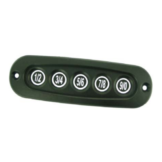
Introduction This manual provides the necessary information for the proper installation and use of TriMark’s Relay e-PAD Keypad. The Relay e-PAD Keypad includes: e-PAD (keypad user interface) - Keypad integrated grab handle. Clean acrylic rod with mild soap and water only. -
Page 4: Standard E-Pad Mode Operation And Features
Standard Mode e-PAD Operation and Features This mode is primarily intended for controlling an actuator that will lock or unlock a door’s security feature (cam lock, deadbolt, etc.) The e-PAD is shipped with default Authority and Access Codes. If the OEM or dealer has not changed default codes, the Authority and Access Codes are: Access code:... -
Page 5: Autolatch E-Pad Mode Operation And Features
AutoLatch Mode e-PAD Operation and Features This mode is available in the 29810-05 version of the keypad only. It is primarily intended for unlatching operations for a cabinet or door, where activation of the keypad physically releases the door from the closed and latched position. -
Page 6: More E-Pad Features
More e-PAD Features Protective Deactivating Security Feature If a correct code is not entered after 20 button presses, the keypad enters an inactive mode that disables button recognition for 1 minute. This helps prevent unauthorized access by entering random codes. There is no button feedback while the system is disabled. -
Page 7: Teaching Keypad New Authority And Access Codes
Access Codes. The Authority Code must be EXACTLY 5 digits long. There are two ways to set the Authority Code with the TriMark Full Feature System. Changing the Authority Code erases all previous Access Codes and sets a new Access Code in memory bank 1 that is the same as the new Authority Code. -
Page 8: Assign New Access Codes
Assign New Access Codes The Access Codes are used to unlock or unlatch the door. The Access Codes must be EXACTLY 5 digits long. With a valid Authority Code, an Access Code can be programmed with the following instructions: 1. Press the (5 / 6) button for 5 seconds until the keypad beeps. The backlighting of the keypad will flash (if equipped) indicating the keypad is in “Learn Mode.”... -
Page 9: Troubleshooting
Troubleshooting Problem Description Possible Solution e-PAD Hints Check the contacts in the door frame (if keypad is installed in door). Dirt and corrosion will hinder power from reach- ing the keypad. Clean with a scouring pad and mild solution. Check for a blown fuse protecting the No response when buttons keypad’s circuit. - Page 10 Remote transmitter FOBs, batteries, and other equipment subject to normal wear and deterioration may need to be replaced periodically by dealer and/or end user and are not covered by this warranty. TriMark will not be liable for indirect, special, incidental or consequential damages.
-
Page 11: Appendix
Appendix: Installation and Mounting e-PAD Wiring Red—12V power Black—Ground Green—Unlock output (12V pulse) Blue—Lock output (12V pulse) Yellow—Authority learn wire (disconnected unless programming) Power wires = female 1/4” spade terminal with one meter wires. Output wires = female 4mm bullet terminal with 200mm wires. Mounting Information (units in metric) - Page 12 UM28 34295-01 03/15-5...
Need help?
Do you have a question about the e-ASK UM28 and is the answer not in the manual?
Questions and answers