Table of Contents
Advertisement
Quick Links
UM1016
User manual
Getting started with the STEVAL-ISV002V2, 3000 W
photovoltaic converter for grid connected applications
Introduction
This document describes the procedure and steps to follow in order to correctly operate the
3 kW STEVAL-ISV002V2 photovoltaic converter. This system consists of an isolated DC-DC
converter and a full bridge inverter used to deliver sinusoidal current at 50 Hz to the grid.
The system operates with input voltages in the range of 200 V to 400 V and is tied to the grid
at 230 Vrms, 50 Hz, through an LCL filter. The demonstration board is provided with a fully
digital control algorithm, including power management for grid-connected operation and
MPPT (maximum power point tracking) algorithm. This has been implemented on a
dedicated control board, equipped with the latest generation 32 bit STM32F103ZE
microcontroller.
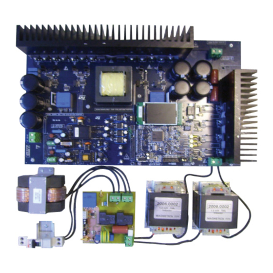
Figure 1.
3 kW PV system image
February 2011
Doc ID 18125 Rev 1
1/19
www.st.com
www.BDTIC.com/ST
Advertisement
Table of Contents

Related Manuals for ST STEVAL-ISV002V2

Summary of Contents for ST STEVAL-ISV002V2
-
Page 1: Figure 1. 3 Kw Pv System Image
This document describes the procedure and steps to follow in order to correctly operate the 3 kW STEVAL-ISV002V2 photovoltaic converter. This system consists of an isolated DC-DC converter and a full bridge inverter used to deliver sinusoidal current at 50 Hz to the grid. - Page 2 Revision history ......... . . 18 2/19 Doc ID 18125 Rev 1 www.BDTIC.com/ST...
-
Page 3: Table Of Contents
Figure 3. Description of the STEVAL-ISV002V2 main parts ....... . 5 Figure 4. -
Page 4: Figure 2. Block Scheme Of Hardware Implementation
System description Figure 2 is a block scheme representing the hardware implementation adopted for the STEVAL-ISV002V2 demonstration board. Figure 2. Block scheme of hardware implementation It consists of 5 PCBs electrically connected by means of suitable connectors. The 5 PCBs are listed below and are hereafter referred to with the following nomenclature: ●... -
Page 5: Figure 3. Description Of The Steval-Isv002V2 Main Parts
+/-15 V for LEM sensor supply ● 24 V for relay supply Figure 3. Description of the STEVAL-ISV002V2 main parts Figure 3 shows a more detailed description of the hardware implementation according to the nomenclature used above. The main power board is highlighted in yellow and clearly shows the way it hosts two ancillary boards: the multi-output power supply board and the control board with STM32F103ZE. -
Page 6: Figure 4. Coupling Inductors Wiring
J9. It is important to underline that while the filter inductors have the two wires connected between J7 and J8, both the wires of the coupling inductor are connected to J9. 6/19 Doc ID 18125 Rev 1 www.BDTIC.com/ST... -
Page 7: Figure 6. Connectors Used For The Sensing Signals
J15 which is placed on the output sensing and relay board. The wire carrying the signal proportional to the grid injected current is connected to J9, placed on the microcontroller board, and to J14 which is soldered on the sensing and relay board. Doc ID 18125 Rev 1 7/19 www.BDTIC.com/ST... -
Page 8: Figure 7. Connectors Used For Power Supply And Relay Command
J1 and J12, placed on the microcontroller board and output sensing board respectively. Figure 8 shows a close-up of the output sensing board and provides clear instructions on how to correctly carry out the wiring of this part of the system. 8/19 Doc ID 18125 Rev 1 www.BDTIC.com/ST... -
Page 9: Figure 8. Wiring Setup Of The Output Sensing And Relay Board
9, can be used to either connect an electrical load when testing the DC-DC converter or to connect a DC power supply when testing the DC-AC inverter. Figure 9. Input and output power connectors Doc ID 18125 Rev 1 9/19 www.BDTIC.com/ST... -
Page 10: Figure 10. First Screen Shot Shown On The Lcd Display At Startup
Connect a suitable electrical load to connector J7. Keep the filter inductors wire connected on J7 as well. Move the joystick up to select the next window on the LCD display. The screen shot of Figure 12 appears. 10/19 Doc ID 18125 Rev 1 www.BDTIC.com/ST... -
Page 11: Figure 12. Closed Loop/Open Loop Selection Window
Push the joystick to enable the control loop modulation. The display shows the screen shot in Figure 14, indicating that the control loop state is in start. Doc ID 18125 Rev 1 11/19 www.BDTIC.com/ST... -
Page 12: Figure 14. Screen Shot With Control Loop State In Start
The amount of power delivered to the electrical load depends also on the value of the inverter modulation index. The default value is very low and is shown in Figure 12/19 Doc ID 18125 Rev 1 www.BDTIC.com/ST... -
Page 13: Figure 16. Dc-Ac Converter Control Window
Connect J1 on the power supply board to 230 V AC and power the system up ● Reset the microcontroller firmware and make sure the screen shot shown on the display is the one in Figure 17: Closed Loop - Control State 0-stop. Doc ID 18125 Rev 1 13/19 www.BDTIC.com/ST... -
Page 14: Figure 17. Lcd Display Screen Shot After Microcontroller Reset
Do not enable the DC source while setting the voltage value ● Enable the DC source ● Push the joystick button ● The LCD display shows that the firmware is now in start mode, as shown in Figure 19 14/19 Doc ID 18125 Rev 1 www.BDTIC.com/ST... -
Page 15: Figure 19. Lcd Display Showing The Closed Loop Control Is In Start Mode
At this point the systems would be grid connected if the coupling inductor was not disconnected. ● The LCD display shows the screen shot in Figure 21, with the control state update from start to grid insertion Doc ID 18125 Rev 1 15/19 www.BDTIC.com/ST... -
Page 16: Figure 21. Control State "Grid Insertion
The system injects a few tens of Watts into the grid ● To increase the current injected into the grid you can either: – Increase the DC source voltage – Increase the phase shift value on the DC-DC converter control menu. 16/19 Doc ID 18125 Rev 1 www.BDTIC.com/ST... -
Page 17: Figure 22. Control Parameters Tuning
Verify that the injected power is a few tens of Watts ● Disconnect the grid and disable the DC input source ● Do not press reset as long as any voltage (except auxiliary voltages) on the power board is present. Doc ID 18125 Rev 1 17/19 www.BDTIC.com/ST... - Page 18 Revision history UM1016 Revision history Table 1. Document revision history Date Revision Changes 09-Feb-2011 Initial release. 18/19 Doc ID 18125 Rev 1 www.BDTIC.com/ST...
- Page 19 No license, express or implied, by estoppel or otherwise, to any intellectual property rights is granted under this document. If any part of this document refers to any third party products or services it shall not be deemed a license grant by ST for the use of such third party products or services, or any intellectual property contained therein or considered as a warranty covering the use in any manner whatsoever of such third party products or services or any intellectual property contained therein.
Need help?
Do you have a question about the STEVAL-ISV002V2 and is the answer not in the manual?
Questions and answers