Advertisement
Advertisement
Table of Contents

Related Manuals for ADENDORFF MC900

Summary of Contents for ADENDORFF MC900
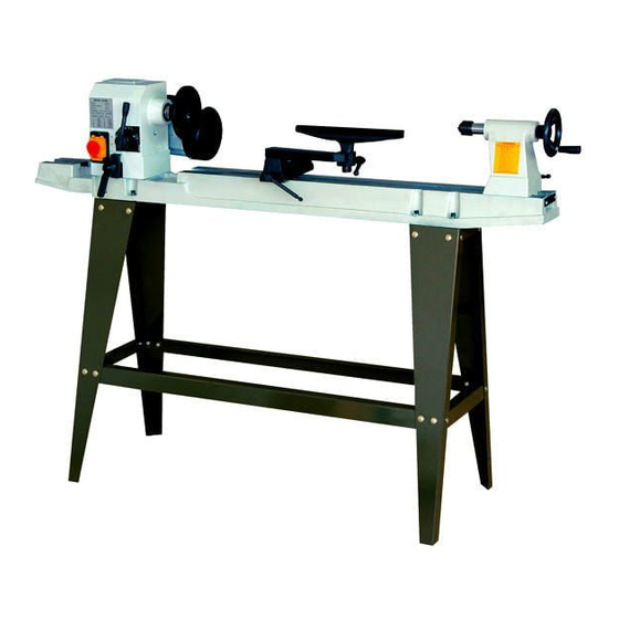
- Page 1 V AR/ABLE SPEED WOOD LATHE MC900 MCll00 Instruction Manual...
-
Page 2: Table Of Contents
VI I. Ad j ustments ..........12 VIII. Operation ............13 IX . Maintenance ........... I • Technical data VARIABLE SPEED WOOD LATHE MODEL NUMBER MC900 MC1100 220-240V 110-120V Voltaae Speeds... -
Page 3: General Safety Rules
I . General safety rules Safety is a combination of common sense, staying alert and knowing how your wood lathe works. WARNING: TO AVOID MISTAKES THAT COULD CAUSE SERIOUS INJURY, DO NOT PLUG THE WOOD LATHE IN UNTIL THE FOLLOWING STEPS HAVE BEEN READ AND UNDERSTOOD. -
Page 6: Electrical Information
Specific safety rules for the wood lathe-Continued 16. leave the work area only after the lathe's motor has come to a (ull stop. 17. Hang your turning tools on the wall beyond the tailstock end of the lathe. Do not lay them on the bench so that you must reach over the revol' ing workpiece to select them. -
Page 9: Vi • Assembly
VI • Assembly Fig. 1 ult'le bed U1emety ======�=It]) c:z:: « :, Push rod �--� \\-� '4hox keys wi• 2 - 32mm ftaf IChe9 3.-4,8,8 mm • • • '------- ----- -----191----- --- - ----- -..1... - Page 10 VI • Assembly Erecting the leg set (Figure 2) Fi g . 2 1. Attach one front and one back leg [1] to the outside edge of the top plate [2] using carriage bolts [3], washers [4], and nuts [SJ. •...
- Page 11 spindle using the two wrenches provided [2] VI • Assembly Spurs 1. Remove the faceplate [1] from the headstock to separate the faceplate from the spindle nut. (Figure 5) 2. Insert the headstock spur [31 in the spindle hole. 3. Insert the tailstock center (4] in the tailstock hole.
-
Page 13: Operation
--- -- -- - - - ----- -- ·-··· · -- ·- -- Vll. Operation Switch (Figure 12) 1. To tum the lathe •oN•, insert the yellow switch Fig. 12 key Into the switch housing. 2. Move the switch to the •oN· position. 3. - Page 15 MC900...
- Page 17 MCllOO PART LIST Q'TY DESCRIPTION I Q'TY DESCRIPTION HEX WRENCH HEADSTOCK BOLT-A FACEPLATE CLAMP-A DRIVING CENTER HEX NUT SPINDLE ANGULAR SETTING ASSEMBLY SCR!W BEARING SPINDLE WRENCH .,C" RING GEAR ASSEMBLY SPRING SPEED LABLE BRACKET -SHIFING LEVER INSTRUCTION MANUAL "C" RING HEX SCREW "C"...
Need help?
Do you have a question about the MC900 and is the answer not in the manual?
Questions and answers