Advertisement
Quick Links
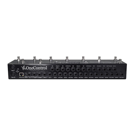
OC 10 Crocodile Tail Loop Setup Utilising Tuner Out And One Loop
The above setup is using the OC10 in it's most basic form were the guitar signal is run directly into
the rear main input jack.
The tuner output is selected when the OC10 is in program mode via the top row left hand footswitch
labelled "TUNER/L10", when selected this mutes all output from unit except signal running from tuner
jack output.
Loop 1 is being utilised in this example. loops 1 thru 7 are internally connected so signal from main
input will always be running to OUT 1 and OUT 2 whether pedals are connected or not.
OUT 2 is being utilised in this example to run directly to amp input, OUT 1 and OUT 2 are in parallel
and are both supplied signal from the input jacks through loops 1 to 7, OUT 1 would be utilised if sig-
nal was required to run directly into IN 8 which is the start of the second run of loops (8,9,10)
SETUP 1
KEY
All Red Lines Are Cables
Taking Signal Into OC10
All Green Lines Are Cables
Taking Signal Out Of OC10
Advertisement

Subscribe to Our Youtube Channel
Related Manuals for One Control Crocodile Tail Loop

Summary of Contents for One Control Crocodile Tail Loop
- Page 1 Taking Signal Out Of OC10 SETUP 1 OC 10 Crocodile Tail Loop Setup Utilising Tuner Out And One Loop The above setup is using the OC10 in it’s most basic form were the guitar signal is run directly into the rear main input jack.
- Page 2 All Red Lines Are Cables Taking Signal Into OC10 All Green Lines Are Cables Taking Signal Out Of OC10 SETUP 2 All Purple Lines Are Cables Taking Signal Out of OC10 OC10 Setup Utilising Buffer Circuit, 1 Loop and Immediately Back Into from Loops 1 thru 7 and Loop 8 OC10 ...
- Page 3 SETUP 2 PAGE 2 In this example you can see that the echo unit in Loop 8 is connected via the S8 (Send 8) and R8 (Return 8) sockets, unlike Loops 1 thru 7 which are all internally connected, Loops 8 Thru 10 are not and must be linked together using the Out and In sockets from each loop to run the signal into the next loop.
- Page 4 All red lines are cables taking signal into OC10 All green lines are cables taking signal out of OC10 SETUP 3 All purple lines are cables taking signal out of OC10 OC10 setup utilising BJF buffer Circuit, 4 loops from Loops and immediately back Into 1 Thru 7, Loops 8 And 9 for effects and Loop 10, S10 (N.C) OC10 (Links)
- Page 5 SETUP 3 PAGE 2 In setup 3 we utilise the buffer circuit, 4 loops from loops 1 to 7, loops 8 and 9 and loop 10 as a Ctrl switch to switch channels on our amplifier. Utilising the Buffer circuit will give the signal increased strength and retention of clarity, primarily this circuit is designed for running longer cable runs and running through multiple effects units which ulti- mately can lower signal strength and dull the top end of the signal.
- Page 6 All red lines are cables taking signal into OC10 All green lines are cables taking signal out of OC10 SETUP 4 All purple lines are cables taking signal out of OC10 OC10 setup utilising BJF buffer Circuit, 4 loops from Loops and immediately back Into 1 Thru 7 running to amplifier front input and Loops 8 and 9 OC10 (Links)
- Page 7 SETUP 4 PAGE 2 In setup 4 we utilise the buffer circuit, 4 loops from loops 1 to 7 which are then running directly into the amplifier input, using the FX send of the amp we are returning the signal into loop 8 through loop 9 and then back to the FX return of the amplifier.
- Page 8 All red lines are cables taking signal into OC10 All green lines are cables taking signal out of OC10 SETUP 5 All purple lines are cables taking signal out of OC10 OC10 setup utilising BJF buffer Circuit, 4 loops from Loops and immediately back Into 1 Thru 7 running to amplifier front input and Loops 8 and 9 OC10 (Links)
- Page 9 SETUP 5 PAGE 2 In setup 5 we utilise the buffer circuit, 4 loops from loops 1 to 7 which are then running directly into the amplifier input, using the FX send of the amp we are returning the signal into loop 8 through loop 9 and then back to the FX return of the amplifier.
Need help?
Do you have a question about the Crocodile Tail Loop and is the answer not in the manual?
Questions and answers