
Summary of Contents for Weston 2VL1
- Page 1 2VL1 Dual VCO + LFO DIY Eurorack Module Weston Precision Audio Designed In Portland, Oregon © 2019 Weston Precision Audio Revision 03 - August 29 2019...
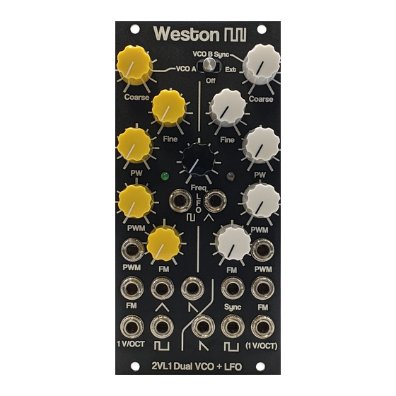
- Page 2 DESCRIPTION SPECS, cont. The 2VL1 is a compact (12HP) Eurorack All wave outputs: 10 Volts peak-to-peak format synthesizer module which includes 2 VCOs and 1 simple LFO. The VCO 1 range: 1Hz - 20kHz 2VL1 was designed with the idea of VCO 2 range;...
- Page 3 © 2019 Weston Precision Audio...
-
Page 4: Build Instructions
Start with diodes, resistors, ferrite BUILD INSTRUCTIONS beads, then caps, then DIP sockets and Begin by stuffing PCB-A using the table connectors, and finally transistors and below. trimpots. 2VL1 PCB-A Rev AC Stuffing Reference Quantity Value Footprint/Note C10 C11 2 10n Film (WIMA) Capacitor_THT:C_Rect_L7.0mm_W6.0mm_P5.00mm... - Page 5 BUILD INSTRUCTIONS, cont. Next, stuff PCB-B using the same parts order as the previous board. 2VL1 PCB-B Rev AD Stuffing Reference Quantity Value Footprint/Note C19 C20 C21 C22 C23 C24 C25 C26 8 0.01u Film Capacitor_THT:C_Rect_L7.0mm_W2.5mm_P5.00mm C27 C28 2 1.5u Film Capacitor_THT:C_Rect_L7.0mm_W2.5mm_P5.00mm...
- Page 6 RV1 RV10 RV2 RV3 RV4 RV5 RV6 RV7 RV8 RV9 10 100K LIN Install square and level! Don’t forget to solder the 2 retention tabs. They are grounds! 1 SYNC SOURCE Switches:Apem MHS233K 2P3T © 2019 Weston Precision Audio...
- Page 7 2) Monitor VCO1 saw output with your look good with a resistor value of O-scope and adjust SAW1 SHAPE 4.7KOhm or higher. If the oscillating trim pot to connect the halves of the currents for lighting the LFO LED are saw. © 2019 Weston Precision Audio...
- Page 8 2VL1, but any other VCOs on your Eurorack as well. The transistor circuit and 150uF cap on PCB-C help mitigate these ripples to a great degree, but it’s still best to avoid high-current LEDs as well (“Belt and suspenders”).
- Page 9 REF (PCB Pics Finished) © 2019 Weston Precision Audio...
- Page 10 SCHEMATICS (PCB-A) © 2019 Weston Precision Audio...
- Page 11 SCHEMATICS (PCB-B) © 2019 Weston Precision Audio...
- Page 12 SCHEMATICS (PCB-C) © 2019 Weston Precision Audio...
Need help?
Do you have a question about the 2VL1 and is the answer not in the manual?
Questions and answers