Table of Contents
Advertisement
Quick Links
Advertisement
Table of Contents

Related Manuals for Newport Elite 3

Summary of Contents for Newport Elite 3
- Page 1 Artisan Technology Group is your source for quality new and certified-used/pre-owned equipment SERVICE CENTER REPAIRS WE BUY USED EQUIPMENT • FAST SHIPPING AND DELIVERY Experienced engineers and technicians on staff Sell your excess, underutilized, and idle used equipment at our full-service, in-house repair center We also offer credit for buy-backs and trade-ins •...
- Page 2 Elite 3 Active Isolation Workstation/ Active Isolation Module Instruction Manual PERATOR ANUAL Artisan Technology Group - Quality Instrumentation ... Guaranteed | (888) 88-SOURCE | www.artisantg.com...
- Page 3 Notes: Artisan Technology Group - Quality Instrumentation ... Guaranteed | (888) 88-SOURCE | www.artisantg.com...
- Page 4 Elite 3 Active Isolation Workstation/ Active Isolation Module Instruction Manual © Newport Corporation Irvine, California, USA Part No. 23666, Rev D IN-12971 (10-98) Section 1 — Introduction Artisan Technology Group - Quality Instrumentation ... Guaranteed | (888) 88-SOURCE | www.artisantg.com...
- Page 5 This warranty is in lieu of all other warranties, expressed or implied, including any implied warranty of merchantability or fitness for a particular use. Newport Corporation shall not be liable for any indirect, special, or consequential damages. Artisan Technology Group - Quality Instrumentation ... Guaranteed | (888) 88-SOURCE | www.artisantg.com...
-
Page 6: Table Of Contents
2.7 Retro-Fitting AIM to the VH IsoStation .......... 2-10 Section 3 — Operation ................3-1 3.1 Power Up: Systems Integrated by Newport Corporation ....3-1 3.2 Power Up: Systems Integrated By the Customer......3-2 3.3 Controller Front Panel Controls ............3-2 3.4 Technician interface to controller ............ - Page 7 6.1 Spare Parts List ..................6-1 Isolators: ....................6-1 Cables:....................6-1 Controller: ....................6-1 Section 7 — Elite 3 Firmware and Software ......7-1 7.1 Scope ....................7-1 7.2 Firmware and Software Installation into PC ........7-1 7.3 Firmware Selection ................7-2 7.4 Firmware Downloading................
- Page 8 2.1 Leveling Pad Adjustment ................2-2 2.2 Shipping Locks ..................2-3 2.3 Horizontal Damping Oil Installation ............2-4 2.4 Elite 3 – Controller Rear Panel ..............2-5 2.5 Installing the Controller and Cabling ............2-6 2.6 Cable Manager Installation ..............2-9 2.7 Ground Strap Attachment ..............2-10 3.1 Elite 3 Front Panel Controls ..............3-3...
- Page 9 Notes: Artisan Technology Group - Quality Instrumentation ... Guaranteed | (888) 88-SOURCE | www.artisantg.com...
-
Page 10: Section 1 - General Information
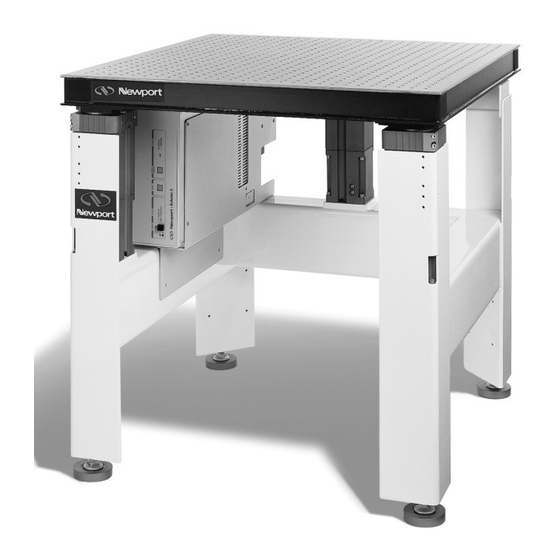
Section 1 — General Information Specifications System Includes: Active Isolation Workstation (AIW): Frame with independent leveling feet for each leg, three (or four) Active Isolation Modules with selection of load range, DSP (Digital Signal Processor) controller and power supply, and a selection of table tops and work surfaces. -
Page 11: Introduction
< 0.75 sec to actuate. Dock/Undock time Settling time after undock is a function of system leveling. Time is < 100 ms seconds for a perfectly leveled system. Shipping Locks Integral with Isolation Modules. ⁄ inch Allen wrench implementation. Rated at >1 g horizontal with maximum per isolator load of 500 lb. - Page 12 • The system is relatively immune to oscillation caused by mechanical resonances in the payload. The elastomer isolator effectively filters out most on-board vibration before it can be sensed by the geophone. • The isolated payload is very stiff vertically. Changes in load center of gravity have little effect on the levelness of the payload during or after stage movement.
-
Page 13: Getting Started
A bubble level is provided to aid in leveling the system. The Active Isolation Systems on Workstations integrated at Newport Corporation are set to a nominal gain level which is suitable for the majority of applications. Small footprint systems where the payload is very high may require gain adjustment to optimize performance. - Page 14 [Note: Back support bar Elite 3 is also compact enough to without armrests also available.] fit in most elevators. Figure 1.2 — Assembly Orientation Section 1 —...
-
Page 15: Safety Terms
The term “Warning” used in the text indicates dangers that could result in personal injury. The term “Caution” indicates situations that may result in damage to the AIM or AIW components. The following International Symbols are used on the Elite 3 controllers. Power on Power off Protective ground... -
Page 16: Warranty Information
Warranty information may be found on the page preceding the Table of Contents of this manual. Should it be necessary to exercise the warranty, contact your Newport representative to determine the correct course of action. Newport Corporation maintains offices in the United States and worldwide. - Page 17 P/N 20387 Front uprights P/N 20389-01 Washer, neoprene P/N 20385 Mount brackets P/N 3664-BA-244 Screw, button HD P/N 21252 Brace P/N 20308 Support arm bracket P/N 20657 H-shaped rear frame P/N 3941-JO-0905-060 Flat washer P/N 20380 Shelf assembly P/N 3751-AF-248 Hex head screw P/N 20305 Support arm corners P/N 3941-0829-048 Flat washer P/N 20306 Support ring tubes...
- Page 18 Figure 1.4 — Caster Installation Section 1 — Introduction Artisan Technology Group - Quality Instrumentation ... Guaranteed | (888) 88-SOURCE | www.artisantg.com...
- Page 19 Notes: 1-10 Artisan Technology Group - Quality Instrumentation ... Guaranteed | (888) 88-SOURCE | www.artisantg.com...
-
Page 20: Section 2 - System Assembly
Section 2 — System Assembly AIW Frame Installation Adjust the leveling pads on the bottoms of the legs as shown in figure 2.1. Rotate the pads until approximately ⁄ inch (9 mm) of thread remains out- side the leg and jam nut. If casters have been ordered, extend the leveling pads to provide floor clearance and fasten the caster assemblies to the frame legs at the pre-drilled and tapped locations on the lower legs (figure 1.4) using the... -
Page 21: Leveling The Frame
Newport integrated systems consisting of frame, isolation modules, and table top will be produced to ensure these condi- tions are met when the system is manufactured. - Page 22 2.3.3 Tighten all armrest and accessory support bolts. See Section 2.6. Release the shipping locks. The shipping locks store by sliding them down and securing them to the isolator bodies with the two screws in the lower two holes. The slotted hole in the shipping lock goes at the bottom. See Figure 2.2.
-
Page 23: Installing The Horizontal Damping Oil
Replace the “fill” plug. See figure 2.3. Systems integrated at Newport Corporation will generally be shipped with the damping oil installed. Figure 2.3 — Horizontal Damping Oil Installation... - Page 24 Merely select a numbering convention and continue to use it. The Elite 3 system is equipped with a high voltage interlock which dis- ables the high voltage power supply if an isolator cable is unplugged or cut.
- Page 25 (4) Mounting Screws (4) Mounting Screws Figure 2.5 — Installing the Controller and Cabling Artisan Technology Group - Quality Instrumentation ... Guaranteed | (888) 88-SOURCE | www.artisantg.com...
-
Page 26: Options Installation
Options Installation These additional assembly steps are necessary to install optional items you may have ordered for your workstation. Support Ring WARNING Install the support ring only after installing the table top or payload. (see Section 2.2) See figure 1.3. Place the four support ring tubes (P/N 20306) in a rectangle on the floor or workbench with the holes in the ends facing up and to the inside of the rectangle. -
Page 27: Equipment Shelves
Equipment Shelves Attach the supplied mount brackets (P/N 20385) to the two front uprights (P/N 20387) and the H-shaped rear frame (P/N 20657) at the desired shelf height. Place the shelves in the uprights and attach to the mount brackets. Attach the corner braces (P/N 21252) between the rear uprights and the top shelf, using the Phillips-head screw already installed on the underside of the shelf to attach the corner brace (see Figure 1.3). -
Page 28: Cable Manager
Cable Manager The cable manager is used to minimize the vibrations transmitted by electrical and supply cables to isolated equipment. Mount the cable manager on the support rail or ring using a base clamp. Place cables and supply lines between the jaws of the cable manager, maintaining as much slack as possible on both sides of the Cable Manager. -
Page 29: Static Dissipative Table Tops
Static Dissipative Table Tops Figure 2.7 indicates how to attach the special ground strap hardware to your Active Isolation Workstation if it includes the static dissipative table top. Table top connection Wrist band Connection to ground Figure 2.7 — Ground Strap Attachment Retrofitting the AIM Active Isolation Module to the VH IsoStation Retrofitting the AIM Active Isolation Module to the VH IsoStation rt model VH IsoStation with no vibration isolation or passive... -
Page 30: Section 3 - Operation
Do not connect or disconnect isolator module cables while power is applied. Power Up: Systems Integrated by Newport Corporation Note: The power supply in the Elite 3 Controller will adjust automatically for 110 or 220 volt AC operation. Those Active Isolation Workstations integrated by Newport will isolate effectively as they are delivered in almost all cases. -
Page 31: Power Up: Systems Integrated By The Customer
Controller Front Panel Controls Three function are controlled from the Elite 3 front panel buttons. The sys- tem status is shown by the combination of colors of the power and the Dock/Undock indicator lights as defined in section 4.1 “Power”... - Page 32 RESET STATUS UNDOCK POWER ON DOCKED UNDOCKED SYSTEM FAULT NEWPORT Active Isolation System ELITE 3 Figure 3.1 – Elite 3 Front Panel Controls Section 3 — Operation Artisan Technology Group - Quality Instrumentation ... Guaranteed | (888) 88-SOURCE | www.artisantg.com...
-
Page 33: Technician Interface To Controller
Technician Interface to Controller Open the terminal program “Elite 3” by running the Elite 3.EXE program. The system control functions are accessed by clicking on the buttons in the upper left screen corner. Button functions: “Exit” Exits the Elite3 terminal and returns to Windows “Lightning Bolt”... -
Page 34: 3.4.1 Setting System Gains
To set the system gains click on the “Reset” button to put the controller in maintenance mode. When the status bar reads “Elite 3 ready for data,” click on the “G” button and merely change the gains on the “Transfer Gains”... - Page 35 Figure 3.3 — Interface Software — Gain Setting Screen The “GF” values control how the Elite recovers from transient shocks which may overload the geophone amplifier or DSP ADC. These values are generally changed only by a factory technician. Nominal values are: 0.9999 0.99999 invGF...
-
Page 36: Interface Connections
Logic ground Not used Not used Not used Not used If system power is interrupted, the docking system will remain in the current docking condition when the power is interrupted. Elite 3 User Interface Controller Circuit OPTO- COUPLER 5 – 24V Figure 3.4 Isolation status output –... -
Page 37: High Voltage Safety Interlock
High Voltage Safety Interlock A high voltage safety interlock is incorporated into the isolation module cables. If any of the cables are unplugged the Elite 3 controller will turn off the 420 volt high voltage power supply. In three isolator systems, the sup- plied jumper plug must be plugged into the unused module connector (generally connector number 4) for the system to function. -
Page 38: Section 4 - Troubleshooting
4.2.5 Confirm that the isolator gains are properly set. See Section 3.3.1. 4.2.6 Confirm That The AC Line Fuses Have Not Blown The Elite 3 is protected by AC line fuses located in the line cord connected on the controller rear panel. See figure 2.4. Replace the fuses with those of the same type and rating. - Page 39 Com Port. The Elite 3 AIC is normally configured to communicate through Com Port 1. The Com Port can be changed with the “Com Port” pull down menu. See figure 3.2 (Elite 3 Terminal Programs earlier than Version 3.0 are configured to communicate through Com Port 1 only).
-
Page 40: Section 5 - Service And Maintenance
1. Model number. 2. Purchase order number. 3. Complete description of the problem. If components are to be returned to Newport Corporation, you will be given a Return Number, which you should reference in your shipping documents. Please fill out the service form on the next page and have the information ready when contacting Newport Corporation. -
Page 41: Cleaning
Cleaning To clean any of the optional work surfaces (either 400 series stainless steel or high pressure laminate) spray household cleaner, such as “409” or “Fantastic”, on a clean cloth and wipe down. Avoid using abrasive cleaners since they will foul the mounting holes and also damage the laminate tops. Powder coated frames may be cleaned in the same manner as the work surfaces. - Page 42 Notes: Section 1 — Introduction Artisan Technology Group - Quality Instrumentation ... Guaranteed | (888) 88-SOURCE | www.artisantg.com...
- Page 43 Newport Corporation Service Form U.S.A. Office: 714/863-3144 FAX: 714/253-1800 Name RETURN AUTHORIZATION # RETURN AUTHORIZATION # _____________________________________________________________________________________ ___________________________ Company (Please obtain prior to return of item) (Please obtain prior to return of item) _______________________________________________________________________________ Address _________________________________________________________________________________ Country Date _________________________________________________________________________________ _______________________________________________________________ P.O.
-
Page 44: Section 6 - Spare Parts
Section 6 — Spare Parts Spare Parts List Isolators: Standard load, non-docking 22971-03 Standard load, docking — with round docking hole in top plate 22971-01 Standard load, docking — with slotted docking hole in top plate 22971-05 High load, non-docking 22971-04 High load, docking —... - Page 45 Notes: Artisan Technology Group - Quality Instrumentation ... Guaranteed | (888) 88-SOURCE | www.artisantg.com...
-
Page 46: Section 7 - Elite 3 Firmware And Software
This manual section describes the firmware version 2.0 and software ver- sion 3.0. Any future revisions will be described in the "Read me" files included on the diskettes supplied with the Elite 3 system. Firmware and software enhancements and revisions will be described in detail in "Read me"... -
Page 47: Firmware Selection
Firmware Selection Elite 3 controllers are factory programmed with the standard firmware (file 2_0std21.a0) and fully operational as received. It is not necessary to download any firmware prior to operation. Firmware files provided on the diskettes offer different control algorithms which may be downloaded by the user. -
Page 48: Firmware Downloading
2_0std21 firmware file) will appear. Click "OK." Click "Run" ("Arrow" button). "Elite 3 Running" message window will appear. Click "OK." "Elite 3 running" message should appear on the bottom bar of the screen. The controller isolation firmware will now be running. Both lights on the front panel should be green. -
Page 49: Firmware And Software Upgrading
Firmware and Software Upgrading Upgrade Procedure: If it is necessary to upgrade either the firmware or the user interface software care must be taken to maintain compatible revision levels during the upgrade. The procedure is a follows: Power up the Elite controller and access it from your PC using the user interface software supplied with the controller. - Page 50 Notes: Section 7 — Firmware and Software Artisan Technology Group - Quality Instrumentation ... Guaranteed | (888) 88-SOURCE | www.artisantg.com...
- Page 51 UNITED KINGDOM Tel: 01 60916868 Tel: 01635 521757 Fax: 01 60916869 Fax: 01635 521348 Visit Newport Online at: http://www.newport.com P/N 23666, Rev. D Newport Corporation, Irvine, California, has IN-12971-2 (10-98) been certified compliant with ISO 9002 by Printed in the USA on recycled paper the British Standards Institution.
- Page 52 Artisan Technology Group is your source for quality new and certified-used/pre-owned equipment SERVICE CENTER REPAIRS WE BUY USED EQUIPMENT • FAST SHIPPING AND DELIVERY Experienced engineers and technicians on staff Sell your excess, underutilized, and idle used equipment at our full-service, in-house repair center We also offer credit for buy-backs and trade-ins •...
Need help?
Do you have a question about the Elite 3 and is the answer not in the manual?
Questions and answers