
Related Manuals for Newport femtoFBG

Summary of Contents for Newport femtoFBG
- Page 1 Newport femtoFBG femtoFBG Technical and Software Manual Revision 2, 29 August, 2019...
-
Page 2: Warranty
RESULTING FROM THE PURCHASE OR USE OF ITS PRODUCTS. First printing 2016 © 2019 by Newport Corporation, Irvine, CA. All rights reserved. No part of this manual may be reproduced or copied without the prior written approval of Newport Corporation. -
Page 3: Confidentiality & Proprietary Rights
The Newport programs and all materials furnished or produced in connection with them (“Related Materials”) contain trade secrets of Newport and are for use only in the manner expressly permitted. Newport claims and reserves all rights and benefits afforded under law in the Programs provided by Newport Corporation. -
Page 4: Technical Support Contacts
Detailed description of the problem If the instrument is to be returned, you will be given an RMA number, which you should reference in your shipping documents. You can also contact the Newport Service Department for additional information or assistance. - Page 5 Newport to install and commission your femtoFBG. We are not able to guarantee the proper operation unless the femtoFBG is installed by a member of the technical staff of Newport or an authorized representative of Newport.
-
Page 6: Safety Precautions
Safety Precautions Warnings and Cautions The following are definitions of the Warnings, Cautions and Notes that are used throughout this manual to call your attention to important information regarding your safety, the safety and preservation of your equipment or an important tip. -
Page 7: General Cautions
Always minimize scattered laser radiation; 1.1.4 femtoFBG Specific Information The femtoFBG TAS is designed in such a way that the laser beam is always inside the enclosure with the exception of the processing area where the sample is exposed to the... - Page 8 Along with maximizing the laser safety, having the side cover in place will help to minimize dust deposition on the optical elements used in the femtoFBG thus limiting cleaning or replacement of dirty or damaged optics.
-
Page 9: General Information
Ti:sapphire (800nm) and ytterbium doped solid state lasers (1040nm/520nm). The femtoFBG is designed as a research tool for the fast prototyping of FBGs. It employs high end motion systems in order to move the fiber around a fixed focused laser beam. The excellent performance of the femtoFBG framework and hardware permits the realization of FBGs of several lengths and in a variety of fibers with great reliability. -
Page 10: Inspection For Damage
Inspection for Damage The femtoFBG is carefully packaged at the factory to minimize the possibility of damage during shipping. Inspect the crate and any packaging material such as boxes or bags for external signs of damage or mishandling. Inspect the contents for damage. If there is visible damage to the instrument or components upon receipt, please inform the shipping company and Newport Corporation immediately. -
Page 11: System Overview
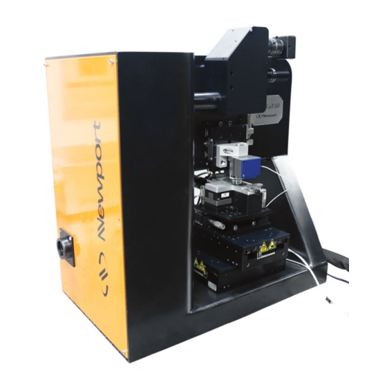
System Overview The approximate dimensions of the femtoFBG are 12 x 20 x 20 in (30.5 x 51 x 51 cm). After locating a suitable location on the optical table where to set the system, the femtoFBG needs to be locked to the table. Figure 1 show an image of the femtoFBG where the stages and imaging assembly have been removed for demonstration clarity. - Page 12 1 and 2, set iris 1 right after mirror 1 and iris 2 right before mirror 2. After setting the location of the irises, their aperture need to be centered with the laser beam path.
- Page 13 The bean travels then through a Glan-laser polarizer by means of the turning mirror M The combination HWP and GLP is used within the femtoFBG to control the amount the laser average power delivered to the sample. The polarization of the laser beam is rendered circular with quarter-wave plate.
- Page 14 Figure 5. Front view of the imaging and focusing setup in the femtoFBG (a). The imaging setup with the front cover displaced so to show the optical elements used in it (b). Figure 6. Optical layout of the femtoFBG imaging and focusing compartments. DM: dichroic mirror;...
- Page 15 Figure 7. Image of the sample assembly showing the motorized and manual stages, and the custom sample holder (a). Schematic of the sample assembly of the femtoFBG (b). X: motorized stage for the x direction; Y: motorized stage for the y direction; TTR: manual tilt, tip, and rotation stage; MC: magnetic clamps.
- Page 16 Figure 8. Lens assembly (IL) in the imaging setup; the locations of the IL variable focus and iris knobs are highlighted. Figure 9. Location of the tilt and tip adjustments of the turning mirror MT in the imaging setup.
-
Page 17: Alignment Procedure
(Figure 4) because of the presence of a focusing plane. Figure 10. During the alignment of the laser beam within the optical layout of the vertical compartment of the femtoFBG, a white piece of paper can be used to check the beam quality after each optical element. - Page 18 Figure 11. The shape and size of the laser beam is visually inspected with the aid of a white piece of paper before (a) and after (b) the OL. In the vertical compartment of the femtoFBG, L and L are used to expand the laser beam diameter so to match or overfill the diameter of the OL back aperture.
- Page 19 Figure 13. Figure 13. Images of the femtoFBG compartment containing the DM. The location of the DM tilt adjustment is shown in (a), while the location of the DM tip adjustment is shown in (b).
- Page 20 The pattern written in the fiber core can easily be programmed using the provided femtoFBG software (Chapter 6). The fiber is sandwiched between a microscope slide (for instance, Ted Pella 26008, 75 x 25 x 1 mm, a starter package is included with the system) and a microscope cover-slip (for instance, Ted Pella 260360, No.
- Page 21 slip. Position the spacers parallel and close to the fiber to be processed in order to not use a lot of index-matching gel. • Using a syringe (not provided) filled with index-matching gel, apply the index- matching gel on top of the fiber to be processed, making sure that it is contained between the two spacers.
- Page 22 Figure 15. Moving the sample in the loading position. Figure 16. Adding the microscope slide.
- Page 23 Figure 17. Setting the fiber to be processed in the V-groves of the magnetic clamps. Figure 18. Clamping down the fiber to be processes.
- Page 24 Figure 19. Setting the two spacers around the fiber. Figure 20. Adding the index-matching gel over the fiber between the two spacers..
- Page 25 Figure 21. Covering the whole assembly with a microscope cover-slip. Figure 22. The sample is position back under the OL and the spacer is removed from the manual TS.
-
Page 26: Software Operation
Run; Tools. Each of these choices will be discussed in the following sections. Figure 23. In order to toggle between the different windows of the femtoFBG software, use the top left icon (a). A list of choices will then appear (b). - Page 27 The “Move” window allows for the accurate positioning of the sample which is a fundamental step in the process of creating a FBG. A large part of the “Move” window is occupied by a live streaming from the CMOS camera. A general overview of all the controls present in the “Move”...
- Page 28 • Increment: Set the length (in µm) of the motion to be performed. In order to choose the axes to move, click the toggle on the left and the X, Y, Z options appear (Figure 25). Once an axis is selected, the interested increment can be added.
- Page 29 • Shutter: the background color changes whether or not the laser is reaching the sample. • Power: the reading from the femtoFBG internal power meter is displayed here. A pull down menu on its right permits to change the scale of the measurement from W to µW.
- Page 30 • Power: the reading from the femtoFBG internal power meter is displayed here. A pull down menu on its right permits to change the scale of the measurement from W to µW. The laser average power displayed here is not the laser average power used at the sample.
- Page 31 Descriptions of specific controls that emerge when a “Profile Type” is chose are defined in the following sections. 6.3.1 Gaussian • Step: distance in µm between points used to interpolate the Gaussian function. Smaller the “step” distance, higher is number of points used for the function interpolation.
- Page 32 • Sin. Min.: minimum value (from 0 to 100%) of Sinus profile. It controls directly the laser output power, and it corresponds to the minimum laser average power used during the FBG writing. An example of a FBG file using the Sinusoidal profile is shown in Figure 28. The FBG is 5 mm long in Y direction and a “Step Size”...
- Page 33 • Stretch: the extent of the Sinc function employed in the chosen FBG length. Two examples showing the effect of the “Stretch” vertical bar are shown in Figure 29. In both cases the FBGs are 5 mm long in Y direction. The maximum and minimum values of the Sinc patterns are set to 100% and o.1% of the laser emission, respectively.
- Page 34 • Start Period: period in µm at the beginning of the pattern. • End Period: period in µm at the end of the pattern. • Step: distance in µm between points used to interpolate the Linear Chirp function. Smaller the “step” distance, higher is number of points used for the function interpolation.
- Page 35 • Step: distance in µm between points used to interpolate the Square Wave function. Smaller the “step” distance, higher is number of points used for the function interpolation. • Max.: maximum value (from 0 to 100%) of the Square Wave profile. It controls directly the laser output power, and it corresponds to the maximum laser average power used during the FBG writing.
-
Page 36: "Run" Window
• Start Vel.: writing velocity in µm/s at the beginning of the pattern. • End Vel.: writing velocity in µm/s at the end of the pattern. • Accel.: acceleration in mm/s use to change the writing velocity from Start Vel. to End Vel. - Page 37 • Shutter: the background color changes whether or not the laser is reaching the sample. • Power: the reading from the femtoFBG internal power meter is displayed here. A pull down menu on its right permits to change the scale of the measurement from W to µW.
- Page 38 Hence, the “Fabrication Velocity” is not active. • Inter-Fab. Velocity: this is the velocity in µm/s used by the femtoFBG when laser writing is not occurring. That is, when the laser shutter is off.
- Page 39 • Z Offset: distance (in µm) between adjacent “repeat” structures in the z direction. • Speed Offset: difference in writing speed (in µm/s) of the inserted “repeat” structures in one row. • Offset %Power: difference in laser average power (in %) reaching the sample for each “repeat”...
-
Page 40: "Tools" Window
“Move” window. “Tools” Window Information regarding the status of the femtoFBG and the ability to perform some specific tasks are in the “Tools” window. The “Tools” window comprise three tabs: Devices, Z-Corrections, and Diagnostics (Figure 37). - Page 41 “Percent Power” control. Figure 38. The variable power attenuator within the vertical section of the femtoFBG needs to be calibrated before use. This task is performed using “Calibrate” in the “Devices” window.
- Page 42 • Get Absolute Offset: it returns the absolute position (in mm) of the stages. • Zero Absolute Offsets: it sets actual positions to origin (0,0,0). • Re-Initialize XYZ Axes: it initializes the stage group used in the femtoFBG. • Open Shutter-server STATUS: it indicates the status of the shuttering system.
- Page 43 • Stage Limits: this window is typical used by Newport Software technical support to monitor the state of the stage assembly if a problem has been reported. FBG Writing Procedure In an FBG, the refractive index of the core is periodically modulated along the fiber’s main axis.
- Page 44 Furthermore, chirped gratings can easily be manufactured by varying the translational speed during the writing process. In this section, a description of the procedure used with the femtoFBG to make a FBG is presented with great details. In this example, the laser employed is Spectra-Physics Spirit.
- Page 45 13. Remember that in the femtoFBG the focused laser beam is fixed and a pattern is created in the sample by moving the sample itself around the laser beam.
- Page 46 Figure 40. The “Video Settings” controls can be used to improve image quality. Figure 41. When centering the fiber in the imaging the field of view the first time, it will be out of focus.
- Page 47 Figure 42. The fiber is put into focus by adjusting the manual translation stage (a) until the borders of the fiber core becomes clear and sharp (b). Figure 43. The “Cross Hair” button is just above the LED 1 one.
- Page 48 LED is used to control the x and y positions of the fiber (b). Producing the File 1. Open the “Design” window in the femtoFBG software. 2. Choose a Gaussian “Profile Type”, a length of 7 mm, the Y-axis for travel, and positive direction.
- Page 49 1.6 µm. Writing the FBG 1. Open the “Run” window in the femtoFBG website. 2. Press “Select” to upload the file made in the section 7.2. 3. Set the “% Power” to 15.0. This is the control of the variable power attenuator within the femtoFBG.
- Page 50 Figure 47. After selecting the “Run” toggle and before the writing of the FBG begins, a window indicating the file preparation by the femtoFBG controller will appears. Figure 48. The top right “Shutter” icon in the “Run” window indicates the status of the shutter...
- Page 51 Figure 49. The fabrication of FBG is best monitored using an OSA. This is the spectral response of the FBG made using the file created in Section 7.
-
Page 52: Appendix I − − − − Key Controls Of Spirit Laser Gui
Appendix I − − − − Key controls of Spirit laser GUI When using Spectra-Physics Spirit laser with Newport’s femtoFBG, there are a series of controls that need to be adjusted in the laser software GUI in order to ensure the successful writing of FBGs. -
Page 53: Appendix Ii − − − − Cabling In The Femtofbg Controller
5. Pulse Enable: it needs to be set to “External” in order to allow the femtoFBG software to control the on/off operation of the laser electro-optical modulator. 6. Analog In: it needs to be set to “Enabled” in order to allow the femtoFBG software to control the amplitude of the laser electro-optical modulator. - Page 54 2. Slot #2: there are two cables, one for end of travel and one for motor power relative to the second (top) XMS stage in the femtoFBG. 3. Slot # 3: One cable that goes to the objective lens piezo collar stage.
-
Page 55: Appendix Iii − − − − Back Compartment Of The Femtofbg
Figure 53. Back compartment of the femtoFBG. A USB hub (1) is used in this compartment to receive the ends of all femtoFBG devices which are USB controlled. In Figure 53 the power cord and the cable connecting it to the laptop have been removed for viewing clarity.
Need help?
Do you have a question about the femtoFBG and is the answer not in the manual?
Questions and answers