Advertisement
Quick Links
Advertisement

Related Manuals for flight of harmony The Sound Of Shadow

Summary of Contents for flight of harmony The Sound Of Shadow
- Page 1 Digital Delay Effect Eurorack Module Kit ~rev1.0~...
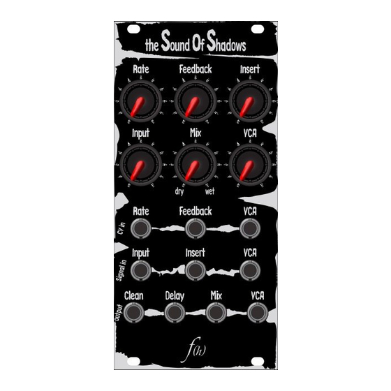
- Page 2 ound hadows Rate Feedback VCA CV Input Rate Feedback Input Insert Clean Delay Specifications Supply Voltage ±12VDC = 51mA = -21mA Supply Current (max draw @ ±12V) Max. Input Voltage (@ ±12V) Max. Output Voltage Direct Input & Ouput (I/O) coupling 1kΩ...
- Page 3 Contents (1) Front Panel (3) PCB- Main, Potentiometer, Jack (3) Resistor Card (1) Semiconductor Card (1) Capacitor Card (1) Hardware bag (1) 9” ribbon cable (1) 2x5 box header (1) 2x5 IDC socket connector with strain relief (1) 2x8 IDC socket connector with strain relief (4) M3x0.5 eurorack mounting screw (4) M3 nylon washer (4) 1x7 pin header (see note)
- Page 4 Overview (taken from SoS-E manual) What is it? The Sound of Shadows (SoS) is a voltage-controlled (VC) digital delay module based around the PT2399 echo IC from Princeton Technology – which was, by the way, originally designed for Karaoke equipment. The SoS is essentially two separate modules: a delay and a voltage-controlled amplifier (VCA).
- Page 5 Overview (cont.) Controls Rate: This controls the delay clock rate, which in turn controls how fast the delay steps through its memory array and thusly the amount of delay. Clockwise rotation increases the rate (which decreases the delay time), counter-clockwise decreases the rate (which increases the delay time).
- Page 6 Overview (cont.) Feedback: This works fig.1 normally, positive increases feedback, negative decreases same. VCA: Same as feedback, positive CV increases the output level, negative attenuates it. Signal in Input: This kind important for a delay unit: you need a signal to delay, or else they’re somewhat dull effects.
- Page 7 Looking at the rear of the module, the negative supply (red stripe) is on the left, positive supply is on the right (see fig.2). Contact: email: flight@flightofharmony.com Twitter: @flightofharmony Drawings and designs ©2019 flight of harmony, LLC. http://www.flightofharmony.com We are tomorrow’s shadows... SoS-K v1.0 instructions Oct. 2019 — p.7/13 www.flightofharmony.com...
- Page 8 PCB Assembled View SoS-K v1.0 instructions Oct. 2019 — p.8/13 www.flightofharmony.com...
-
Page 9: Exploded View
Exploded View SoS-K v1.0 instructions Oct. 2019 — p.9/13 www.flightofharmony.com... - Page 10 SMD Reference SoS-K v1.0 instructions Oct. 2019 — p.10/13 www.flightofharmony.com...
- Page 11 Control & Jack Reference A100k A100k SoS-K v1.0 instructions Oct. 2019 — p.11/13 www.flightofharmony.com...
-
Page 12: Power Cable Assembly
Power Cable Assembly Triangle indicates location of red stripe. SoS-K v1.0 instructions Oct. 2019 — p.12/13 www.flightofharmony.com... - Page 13 Miscellaneous IC1 Orientation LINE Line/Slope Pin 1 Line/Slope Diode Orientation (OR) LINE SoS-K v1.0 instructions Oct. 2019 — p.13/13 www.flightofharmony.com...
Need help?
Do you have a question about the The Sound Of Shadow and is the answer not in the manual?
Questions and answers