Advertisement
COMPU-FIRE® HIGH PERFORMANCE VOLTAGE REGULATOR
FOR HARLEY DAVIDSON® AND AFTERMARKET MOTORCYCLES
Part # 55120 32 Amp Black, OEM #74519-88A, 1989-1999 Big Twins
Part # 55121 22 Amp Black, OEM #74516-86, 1981-1988 Big Twins
Part # 55125 22 Amp Black, 1991-1999 Sportsters
Part # 55130 32 Amp Chrome, OEM #74519-88A, 1989-1999 Big Twins
READ THESE INSTRUCTIONS COMPLETELY BEFORE BEGINNING
INSTALLATION!
Check the contents of the kit:
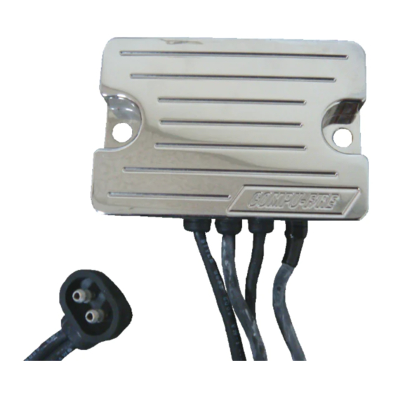
Compu-Fire Regulator
#10 Insulated Ring Lug Terminal
¼" Uninsulated Ring Lug Terminal
5/16" – 3/8" Uninsulated Ring Lug Terminal
NOTE: REFER TO THE FACTORY SHOP MANUAL ELECTRICAL SECTION FOR SAFETY
INSTRUCTIONS PRIOR TO PERFORMING ANY ELECTRICAL SYSTEM REPAIRS OR
MODIFICATIONS!
CAUTION! ALWAYS DISCONNECT THE BATTERY CABLES BEFORE PERFORMING ANY
ELECTRICAL SYSTEM REPAIRS OR MODIFICATIONS.THIS WILL PREVENT DAMAGE TO
THE ELECTRICAL SYSTEM OR COMPONENTS IN CASE OF AN ELECTRICAL ARC
CAUSED BY SHORTING THE BATTERY POWER TO GROUND.
WARNING! SEVERE DAMAGE TO THE ELECTRICAL SYSTEM OR PERSONAL INJURY
MAY OCCUR BY NOT FOLLOWING THE ABOVE SAFETY INSTRUCTIONS.
REMOVAL:
1. Disconnect the cables at the battery. Remove the ground (-) cable first and then
the positive (+) cable.
2. See drawing (Figure 1) to verify correct wire harness for application.
1
INSTALLATION INSTRUCTIONS
024-55120
Advertisement
Table of Contents

Related Manuals for PerTronix Compu-Fire 55120 32

Summary of Contents for PerTronix Compu-Fire 55120 32
- Page 1 024-55120 INSTALLATION INSTRUCTIONS COMPU-FIRE® HIGH PERFORMANCE VOLTAGE REGULATOR FOR HARLEY DAVIDSON® AND AFTERMARKET MOTORCYCLES Part # 55120 32 Amp Black, OEM #74519-88A, 1989-1999 Big Twins Part # 55121 22 Amp Black, OEM #74516-86, 1981-1988 Big Twins Part # 55125 22 Amp Black, 1991-1999 Sportsters Part # 55130 32 Amp Chrome, OEM #74519-88A, 1989-1999 Big Twins READ THESE INSTRUCTIONS COMPLETELY BEFORE BEGINNING INSTALLATION!
- Page 2 024-55120 Measure output lead of original regulator. Cut output lead on Compu- Fire Regulator to same length. Strip wire and crimp #10 insulated ring terminal to wire. NOTE: Crimp must be tight for reliable charging. 4. Install Compu-Fire Voltage Regulator using original hardware. NOTE: Regulator must be mounted in are with good air flow.
- Page 3 If within the period of the foregoing warranty PerTronix finds, after inspection, that the product or any component thereof is defective, PerTronix will, at its option, repair such products or component or replace them with identical...
Need help?
Do you have a question about the Compu-Fire 55120 32 and is the answer not in the manual?
Questions and answers