Table of Contents
Advertisement
Quick Links
Advertisement
Table of Contents

Subscribe to Our Youtube Channel
Related Manuals for MGP Instruments DOSISYS LDM 210


Summary of Contents for MGP Instruments DOSISYS LDM 210
- Page 1 DOSISYS Hands Free Reader LDM 210 - LDM 220 User Manual 128569B...
- Page 3 LDM 210 - LDM 220 Publication, translation and reproduction total or partial of this document is strictly forbidden without authorization MGP Instruments recommends that any work to be done while the instrument is powered should be done by qualified and authorized personnel.
- Page 4 LDM 210 - LDM 220 Table of updates Table of updates Date Issued by Reason for Pages modified modification OCTOBER 28, 2003 J. PEREZ/S. LOPEZ Edit and Translation to English. DECEMBER 16, 2003 J. PEREZ Wrong configuration of the §3-1-2, page 13 two jumpers SS2 and SS3.
-
Page 5: Table Of Contents
Table of contents LDM 210 - LDM 220 Table of contents General ...........................1 Purpose ........................... 1 Of this document ......................1 Nomenclature ........................1 Presentation of the LDM 210 – LDM 220 ................ 1 Description - Functionality....................3 Description of the LDM 210..................... 3 2.1.1 LDM 210 dosimeter reader ................ - Page 6 LDM 210 - LDM 220 Table of contents Corrective Maintenance ....................29 Operating TEST Modes....................29 6.1.1 Operating Modes (SS2 et SS3)................ 29 6.1.2 Test Mode ......................29 6.1.3 AGC amplifier test Mode .................. 29 6.1.4 Autonomous test Mode ..................29 Start-up of Maintenance Modes ..................
- Page 7 Table of figures LDM 210 - LDM 220 Table of figures Figure 1 : Presentation of the LDM 210 reader .................2 Figure 2 : Presentation of the LDM 220 reader .................2 Figure 3 : LDM 210 Assembly Description ..................3 Figure 4 : Description of the LDM 210 enclosure and PCB..............4 Figure 5 : Description of the LDM 210 power pack ................5...
- Page 8 LDM 210 - LDM 220 Table of figures Blank Page 128569B Publication, traduction et reproduction totales ou partielles de ce document sont rigoureusement interdites, sauf autorisation écrite de nos services The publication, translation or reproduction, either partly or wholly, of this document is not allowed without our written consent. Format 112175C...
-
Page 9: General
General LDM 210 - LDM 220 General Purpose Of this document This document provides all the information necessary for the use, configuration and maintenance of the hands free readers models LDM 210 and LDM 220. Nomenclature Symbols " " and " " : These symbols are used for the descriptions and details: The symbol "... -
Page 10: Figure 1 : Presentation Of The Ldm 210 Reader
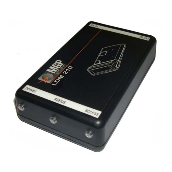
LDM 210 - LDM 220 General Figure 1 : Presentation of the LDM 210 reader Figure 2 : Presentation of the LDM 220 reader 128569B Publication, traduction et reproduction totales ou partielles de ce document sont rigoureusement interdites, sauf autorisation écrite de nos services The publication, translation or reproduction, either partly or wholly, of this document is not allowed without our written consent. -
Page 11: Description - Functionality
Description - Functionality LDM 210 - LDM 220 Description - Functionality Description of the LDM 210 The LDM 210 dosimeter reader is provided with: An RS232 cable, A power supply suitable for use in Europe or U.S. Power supply Cable RS232 Interchangeable plug... -
Page 12: Figure 4 : Description Of The Ldm 210 Enclosure And Pcb
LDM 210 - LDM 220 Description - Functionality Battery carrier Antenna Figure 4 : Description of the LDM 210 enclosure and PCB 128569B Publication, traduction et reproduction totales ou partielles de ce document sont rigoureusement interdites, sauf autorisation écrite de nos services The publication, translation or reproduction, either partly or wholly, of this document is not allowed without our written consent. -
Page 13: Power Supply
The power supply provided is a 9 VDC output wall transformer for the LDM 210. It is connected to JACK J8. Two interchangeable adapters allow the use of the power pack in places with the European or American standard. For other countries, consult MGP Instruments. Figure 5 : Description of the LDM 210 power pack 128569B Publication, traduction et reproduction totales ou partielles de ce document sont rigoureusement interdites, sauf autorisation écrite de nos services... -
Page 14: Identification Label
LDM 210 - LDM 220 Description - Functionality 2.1.3 Identification label Figure 6 : LDM 210 Identification and presentation labels Description of the LDM 220 The LDM 220 dosimeter reader assembly consists of: A plastic enclosure, An integrated USB cable, Three bicolor LED's. -
Page 15: Ldm 220 Dosimeter Reader
Description - Functionality LDM 210 - LDM 220 2.2.1 LDM 220 dosimeter reader The plastic enclosure contains: The reader PCB UC (1). It includes: An Antenna (ANT1) located behind the UC (1) card that allows communication with the dosimeter within a nominal range of 20 to 30 cm. The antenna is attached to the printed circuit board, A 5 pin male connector (J1) for the connection to the USB cable, A 14 pin male connector (J15) for the analog inputs and outputs,... -
Page 16: Identification Label In The Face Of The Ldm 220
LDM 210 - LDM 220 Description - Functionality 2.2.2 Identification label in the face of the LDM 220 Label for vertical fixing Label for horizontal using only (desk) Figure 9 : Identification and front face labels for the LDM 220 128569B Publication, traduction et reproduction totales ou partielles de ce document sont rigoureusement interdites, sauf autorisation écrite de nos services The publication, translation or reproduction, either partly or wholly, of this document is not allowed without our written consent. -
Page 17: Operation
Description - Functionality LDM 210 - LDM 220 Operation Hands free link with the dosimeter PC link RS232 or Reception link Interface Antenna Processor Emission LED’s link IN DIs OUT DOs Batteries Ext. Power Power USB power Figure 10 : LDM 210 and LDM 220 Block Diagram The following operating modes are defined by the position of jumpers in the J16 connector (see §... -
Page 18: Test Mode
LDM 210 - LDM 220 Description - Functionality 2.3.1.1 Retries By default, the reader resends messages 10 times if the dosimeter fails to respond. It is possible to disable the retries by relocating jumper SS4. 2.3.1.2 Reduced range By default, the reader has a normal range of approximately 20 cm. It is possible to reduce the range by relocating jumpers SS5 and SS8. -
Page 19: Installation And Start-Up
Installation and start-up LDM 210 - LDM 220 Installation and start-up Keep the reader away from sources of electromagnetic fields (video terminals, power supplies, PC, rotary machines, etc.) Keep readers away from each other to prevent them from interfering with one another (in case this is not possible, adjust the range of the readers accordingly) Keep readers at least 5 cm (2”) from metallic surfaces. -
Page 20: Ldm 210 And Ldm 220 Configuration
LDM 210 - LDM 220 Installation and start-up LDM 210 and LDM 220 Configuration By default, the reader is delivered from MGP Instruments in "Operating Mode" with retries and with normal range. No jumper is positioned. 3.1.1 Location of jumpers:... -
Page 21: Operating Modes (Ss2 Et Ss3)
Installation and start-up LDM 210 - LDM 220 Figure 12 : Location of jumpers for the configuration of the LDM 220 3.1.2 Operating Modes (SS2 et SS3) These two jumpers are used to configure the reader in the four possible operating modes: Operating Mode Removed... -
Page 22: Operationnal Mode
LDM 210 - LDM 220 Installation and start-up 3.1.3 OPERATIONNAL Mode LDM 210 LDM 220 The operational mode is obtained when jumpers SS2 and SS3 are not installed and the remote programming mode is not selected. In this mode the green power LED is lit after power is applied. Then it is possible to: Authorize reader retries if SS4 is not installed, Forbid them if SS4 is installed. -
Page 23: Installation Of The Usb Driver For The Ldm 220
Installation and start-up LDM 210 - LDM 220 Installation of the USB driver for the LDM 220 Certain software applications like Dosimass, Dosimed and Dosifast automatically install the specific USB driver required by the LDM 220 reader. 3.2.1 For WINDOWS 2000 To verify proper installation of the driver on WINDOWS 2000: Connect the LDM 220 reader to the USB port after installing the driver. - Page 24 LDM 210 - LDM 220 Installation and start-up Open the list of Ports (COM and LPT) and verify the presence of the "COM device" port: "Cypress USB-HID -> COM Device (COM) Note : Disconnect the LDM 220, the Port COM Device disappears. Reconnect the LDM 220, the Port COM Device reappears.
-
Page 25: For Windows Xp
Installation and start-up LDM 210 - LDM 220 3.2.2 For WINDOWS XP 3.2.2.1 Verify the installation of the USB driver To verify proper installation of the driver on WINDOWS XP: Connect the LDM 220 reader to the USB port after installing the driver. From WINDOWS, select the My Computer icon and right click. - Page 26 LDM 210 - LDM 220 Installation and start-up Note : Disconnect the LDM 220 and the Port COM Device disappears. Reconnect the LDM 220 and the Port COM Device reappears. If the USB driver installation is not successful: Reinstall the driver starting from the file "HidComInst.exe" found in the installation CD-ROM.
- Page 27 Installation and start-up LDM 210 - LDM 220 Choose "Install from a specified location" and click on "Continue". Choose "Find the best option at this location", choose "Include this location in the search", click on "Continue“ and select the directory containing the "Ccport.sys" driver.
- Page 28 LDM 210 - LDM 220 Installation and start-up Select "Cypress USB-HID -> COM device" then click "Continue". On the device screen with WINDOWS XP compatibility, click "Continue". Click on "End". 128569B Publication, traduction et reproduction totales ou partielles de ce document sont rigoureusement interdites, sauf autorisation écrite de nos services The publication, translation or reproduction, either partly or wholly, of this document is not allowed without our written consent.
-
Page 29: Operation
Keep readers at least 5 cm (2”) from metallic surfaces. The reader has no stand-alone function; it must be used connected to a PC using software provided by MGP Instruments. Three bicolor LED’s inform users about the status of exchange sequences with the dosimeter. -
Page 30: Recommendation Of Use
LDM 210 - LDM 220 Operation Recommendation of use 4.1.1 LDM210 LDM210 LDM210 Figure 14 : Recommendation of use - LDM210 4.1.2 LDM220 LDM220 LDM220 LDM220 Figure 15 : Recommendation of use - LDM220 128569B Publication, traduction et reproduction totales ou partielles de ce document sont rigoureusement interdites, sauf autorisation écrite de nos services The publication, translation or reproduction, either partly or wholly, of this document is not allowed without our written consent. -
Page 31: Operating Significance Of The Lights
Operation LDM 210 - LDM 220 Operating significance of the lights DESIGNATION VIEW STATUS POWER Reader power is OFF or sending a message to the dosimeter. Lit Green Power OK Lit Red flashes briefly while receiving a message from the dosimeter STATUS Depends on the logic of the software ACCESS... -
Page 32: Reader Usage
They have been specifically adapted for small installations. 4.4.3 Other Software MGP Instruments has developed utilities to help software developers for specific clients. Contact MGP Instruments for further details. 128569B Publication, traduction et reproduction totales ou partielles de ce document sont rigoureusement interdites, sauf autorisation écrite de nos services... -
Page 33: Troubleshooting Guide
(7-9 VDC) Correct the polarity. Start the "VARIOUS TESTS" mode. If the fault persists, return the reader to MGP Instruments. For a battery operated unit: - Check the status of the 2 1.5 V batteries. Replace batteries with new ones with the same characteristics, see §8.3, page 37. - Page 34 LDM 210 - LDM 220 Operation Blank Page 128569B Publication, traduction et reproduction totales ou partielles de ce document sont rigoureusement interdites, sauf autorisation écrite de nos services The publication, translation or reproduction, either partly or wholly, of this document is not allowed without our written consent. Format 112175C...
-
Page 35: Preventive Maintenance
Preventive Maintenance LDM 210 - LDM 220 Preventive Maintenance Not applicable. 128569B Publication, traduction et reproduction totales ou partielles de ce document sont rigoureusement interdites, sauf autorisation écrite de nos services The publication, translation or reproduction, either partly or wholly, of this document is not allowed without our written consent. Format 112175C... - Page 36 LDM 210 - LDM 220 Preventive Maintenance Blank Page 128569B Publication, traduction et reproduction totales ou partielles de ce document sont rigoureusement interdites, sauf autorisation écrite de nos services The publication, translation or reproduction, either partly or wholly, of this document is not allowed without our written consent. Format 112175C...
-
Page 37: Corrective Maintenance
Corrective Maintenance LDM 210 - LDM 220 Corrective Maintenance Operating TEST Modes 6.1.1 Operating Modes (SS2 et SS3) These two jumpers are used to configure the reader in the four possible operating modes: Operating Mode Removed Removed Normal Mode Removed Installed AGC programmable amplifier test Mode Installed... -
Page 38: Start-Up Of Maintenance Modes
LDM 210 - LDM 220 Corrective Maintenance Start-up of Maintenance Modes 6.2.1 REMOTE DOWNLADING AND PROGRAMING Mode In this mode it is possible to download a new version of the software to the reader over the RS-232 link for the LDM-210 model or via the USB port for the LDM-220 model. This new version is stored in the flash memory of the reader DSP chip. -
Page 39: Tests Mode
Corrective Maintenance LDM 210 - LDM 220 6.2.2 TESTS Mode The operating mode of the reader is chosen at start-up. The test modes are usable if the reader is not in the remote downloading mode. Note : The mode can be used with the "HyperTerminal" communication tool from Windows. 6.2.2.1 «... -
Page 40: Reader In "Tests" Mode
LDM 210 - LDM 220 Corrective Maintenance 6.2.3 Reader in "TESTS" mode This mode can be used with any communication program like Windows "HyperTerminal" Select "HyperTerminal" in the Windows accessories. The following screen will appear, enter a name and choose an icon. Validate by pressing OK. - Page 41 Corrective Maintenance LDM 210 - LDM 220 In the following screen fill the required fields with your data Select a port to connect (COM1 for example) Configure the selected port (COM1 for example) and in the field Flux Control , Select None .
- Page 42 LDM 210 - LDM 220 Corrective Maintenance The connection is established. Example of communication with a dosimeter: Software Version Response of dosimeter N° 240729 Polling for response 128569B Publication, traduction et reproduction totales ou partielles de ce document sont rigoureusement interdites, sauf autorisation écrite de nos services The publication, translation or reproduction, either partly or wholly, of this document is not allowed without our written consent.
-
Page 43: Spare Parts, Options
Spare parts, options LDM 210 - LDM 220 Spare parts, options Spare Parts for the LDM 210 Description MGP Instruments Part number Reader Assembly (Europe and U.S. power supply + 127275 RS232 cable) Reader Assembly (Europe power supply. + RS232... - Page 44 LDM 210 - LDM 220 Spare parts, options Blank page 128569B Publication, traduction et reproduction totales ou partielles de ce document sont rigoureusement interdites, sauf autorisation écrite de nos services The publication, translation or reproduction, either partly or wholly, of this document is not allowed without our written consent. Format 112175C...
-
Page 45: Technical Characteristics
Technical Characteristics LDM 210 - LDM 220 Technical Characteristics Mechanical Characteristics of the LDM 210 Length: 110 mm Width 65 mm Depth 28 mm Weight: 110 grams PC to reader cable length: 1.80 m Mechanical Characteristics of the LDM 220 Length: 70 mm Width... -
Page 46: Electrical Characteristics Of The Ldm 220
LDM 210 - LDM 220 Technical Characteristics Electrical Characteristics of the LDM 220 Powered by the USB port: 4.15 V to 5.25 V. Conforms to CE requirements LDM 210 Serial Link J6 female DB9 . Pin number J6 Designation Not used Connected to pin 6 by the PCB Connected to pin 4 by the PCB Connected to pin 8 by the PCB... -
Page 47: Input/Output Digital Dio Ldm 210 And Ldm 220
Technical Characteristics LDM 210 - LDM 220 Input/output digital DIO LDM 210 and LDM 220 Connector J15 male HE10 2x7 pins. 4 inputs and 4 outputs are available on the J15 connector. Pin number J15 Designation INPUT Digital Input 3 INPUT Digital Input 1 OUTPUT Digital Output 1 INPUT Digital Input 2... -
Page 48: Dosimeter Link With Ldm 210 And Ldm 220
LDM 210 - LDM 220 Technical Characteristics Output current 4 mA max. Except DO N°1 8 mA max. -4 mA max. Except DO N°1 8 mA max. Dosimeter link with LDM 210 and LDM 220 Communication with dosimeters in hands free mode: Nominal port (SS5 and SS8 Removed): between 20 and 30 cm Reduced range port (SS5 and SS8 Installed):... -
Page 49: Glossary
Glossary LDM 210 - LDM 220 Glossary A utomatic G ain C ontrol D igital I nput O utput D igital S ignal P rocessor I ntensity O utput H igh I ntensity O utput L ow L ight E mitting D iode P ersonal C omputer R ead O nly M emory RS 232... - Page 50 LDM 210 - LDM 220 Glossary Blank page 128569B Publication, traduction et reproduction totales ou partielles de ce document sont rigoureusement interdites, sauf autorisation écrite de nos services The publication, translation or reproduction, either partly or wholly, of this document is not allowed without our written consent. Format 112175C...
- Page 51 LDM 210 - LDM 220 RETURN REMARKS In order to improve updating of this manual, send us your comments and corrections by electronic mail to the following address: documentation@mgpi.com.fr Your "Return Remarks" will help us to satisfy you. Thank you References to be recalled with the "Return Remarks": Title, reference and index of manual.
- Page 52 F-13113 Lamanon Smyrna, Georgia 30082 Tél. : 33 +(0)4 90 59 59 59 Tel : (770) 432 2744 Fax : 33 +(0)4 90 59 55 18 Fax : (770) 432 9179 Réalisation MGP Instruments – 05/2003 Format 112175C www.mgpi.com 128569B...
Need help?
Do you have a question about the DOSISYS LDM 210 and is the answer not in the manual?
Questions and answers