
Subscribe to Our Youtube Channel
Related Manuals for MGP Instruments DRM-1


Summary of Contents for MGP Instruments DRM-1
- Page 1 OPERATION & CALIBRATION MANUAL DRM Family of Wireless Data Radiation Monitors DRM-1, DRM-1D, DRM-2, DRM-2D Document # 15-00044 Revision 5 April 2008...
- Page 2 Added new features with firmware 071111 for DRM-1 and DRM-2 for 4 threshold settings and selectable using the ‘ACK’ button on the DRM-1 display or DRM-2. Added new screen shots of RMV for threshold settings and instructions The publication, translation or reproduction, either party or wholly, of this document are not allowed without our written consent.
- Page 3 When integrated in the OEM product, these fixed antennas require installation preventing end users from replacing them with non-approved antennas. Any antennas not supplied by MGP Instruments must be tested to comply with FCC Section 15.203 for unique antenna connectors and section 15 emissions.
-
Page 4: Table Of Contents
DRM-1/2 and DRM 1D ........................6 1.1. General Description ........................... 6 Applications for GM Tube (DRM-1, DRM-2) and CsI (DRM-1D) Detectors ......7 DRM-1 Specifications ........................8 General DRM-1 (GM Tube) ......................8 DRM-1D/2D Cesium Iodine (Tl) Specifications ................9 DRM-2 Specifications ........................ - Page 5 10.5 Calibration ............................40 10.6 Linearity ............................42 10.7 Save, Load and Print Calibration and Linearity Certificate ............44 10.8 DRM-1/2 cps To Mr/H Conversion Table ..................45 10.9 DRM-1D cps To Mr/H Conversion Table ..................465 Upgrading the DRM Firmware ....................47 DRM - List Of Electronic Schematics ..................
-
Page 6: Drm-1/2 And Drm 1D
The Data Radiation Monitor - DRM-1/2, is an auto switching two GM-tube based dose rate meter and the DRM- 1D is a sensitive CsI (Tl) scintillated coupled to a PMT. The DRM-1/2 are dose rate meters for detection, using state-of-the-art microprocessor-based technology and combined with telemetry using the WRM2 900 MHz or 2.4 GHZ FHSS radio. -
Page 7: Applications For Gm Tube (Drm-1, Drm-2) And Csi (Drm-1D) Detectors
15-00044 Revision 5 April 2008 1.2 Applications for GM-Tube (DRM-1, DRM-2) and CsI (DRM- 1D) Detectors Perimeter & Boundary Surveillance Vehicle Access Points Turnstile entries Collection of Survey Data for Real-time Mapping & Surveillance Software General Area Monitoring Hospital Emergency Room Entrances and CBRNE storage areas... -
Page 8: Drm-1 Specifications
15-00044 Revision 5 April 2008 2. DRM Specifications 2.1 DRM-1 General (GM Tube) • Detector GM tube ZP-1301 (or equivalent) - high range GM tube ZP-1201 (or equivalent) - low range Optional GM tube ZP-1300 non-energy compensated – low range Optional CsI (Tl) detector •... -
Page 9: Drm-1D/2D Cesium Iodine (Tl) Specifications
15-00044 Revision 5 April 2008 • Optional Accessories Remote Display Unit (external visual & audible alarm) Magnet attachments 2.2 DRM-1D/2D Cesium Iodine (TL) Specifications • Detector: CsI (Tl) (30 x 30 mm) crystal optically coupled to PMT with 0.5 mm aluminum housing and solid mu metal shield. -
Page 10: Drm-2 Specifications
15-00044 Revision 5 April 2008 • Power source External power supply and battery backup External power supply: Input 120-250 Vac, Output 9 to 15 Vdc with locking connector Battery back-up: Three (3) 1.2v NiMH 2100mA rechargeable Battery operating lifetime: Up to 8 hours of continuous operation (with optional Alarm and Display Unit: 4 hours) Power Saving Mode On/Off using Meter View Software •... - Page 11 15-00044 Revision 5 April 2008 Battery back-up: Three (3) 1.2v NiMH 2100mA rechargeable Battery operating lifetime: Up to 12 hours of continuous operation Power Saving Mode On/Off using Meter View Software • Display – LCD Readout: 4 digits for accurate and easy display Detector failure Low battery Overflow...
-
Page 12: Drm Outline Drawings
15-00044 Revision 5 April 2008 2.4 DRM Outline Drawings The publication, translation or reproduction, either party or wholly, of this document are not allowed without our written consent. - Page 13 15-00044 Revision 5 April 2008 2.4 DRM Outline Drawings (continued) The publication, translation or reproduction, either party or wholly, of this document are not allowed without our written consent.
- Page 14 15-00044 Revision 5 April 2008 2.4 DRM Outline Drawings (continued) DRM-1 Inside View The publication, translation or reproduction, either party or wholly, of this document are not allowed without our written consent.
-
Page 15: Drm-1D Outline Drawings
15-00044 Revision 5 April 2008 2.5 DRM-1D Outline Drawings DRM-1D Inside View The publication, translation or reproduction, either party or wholly, of this document are not allowed without our written consent. -
Page 16: Over The Air Communications
For radiation field fluctuations between 2.5 mR/h and 6 mR/h, the response time will be 10 DRM-1/2D Response Times for the CsI (TL) Detector The instrument’s response time is less then 2 seconds once the radiation intensity at the reference point increases or decreases by a factor of 10. -
Page 17: Operating Instructions
The unit is not supplied with an On-Off switch. 3.2.6 NOTE: (Firmware >= 071111 (MARCH 2008) and board updates) By pressing the ‘ACK ‘button once on the DRM-1 external display or the DRM-2 will show the current threshold rate thr.0 setting, then the rate setting i.e.,... -
Page 18: Meter Connectors
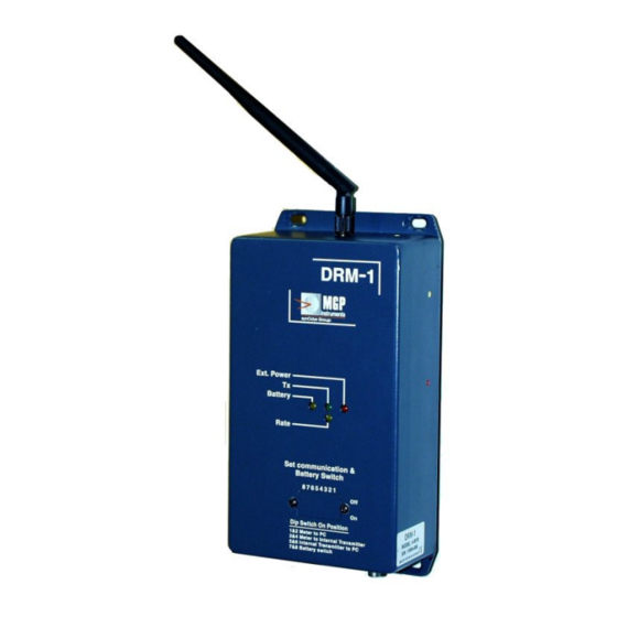
15-00044 Revision 5 April 2008 3.3 Meter Connectors 3.3.1 Connectors: The DRM-1 contains three connectors: 1. 2.5 mm External power supply connector (type L712RA supplied by Switch craft, center post is positive) 6 to 15v DC Ground (-) 2. D-type 9 pin female for RS232 communication port 3. -
Page 19: Power Supply & Battery
15-00044 Revision 5 April 2008 3.3.2 External Connectors: Meter to PC RS232 Cable D-type 9 pin female D-type 9 pin male Meter to External Display & Alarm Unit (lengh 25') Display & Alarm Unit Meter D-type 9 pin female D-type 9 pin female Power Supply &... -
Page 20: General Functions
15-00044 Revision 5 April 2008 4. General Functions 4.1 Dipswitch Selector To set the dipswitch, unscrew two screws located at the meter front panel and remove the dipswitch cover. The dipswitch (8 switches) is located on the meter’s front panel. Using these dipswitches you can setup two functions: a) Communication mode, and;... - Page 21 15-00044 Revision 5 April 2008 • Set switch 7&8 to the OFF position only in case the meter is being stored. Important Note: For operational/configuration settings ensure dipswitches 1, 2, and 3 (dipswitch 3 is for transmitting data) are in the ON position. For field use ensure dip switches1, 2, 3, 7 and 8 are turned ON (7 and8 are for battery backup).
- Page 22 For the DRM-1/2D, the Automatic Background Subtraction is set (using the RMV software) by changing the ‘Background’ number to ‘9999’. The DRM-1/2D will count the background for 60 seconds and then set the current background internally. To ensure a new update for the backgrounds, turn off dipswitches 7 and 8 and unplug the AC adapter from power.
- Page 23 15-00044 Revision 5 April 2008 The ‘Power Saving Mode’ will be activated after the send code ‘8888’ (via RMV in the Background icon) is entered, sent and updated. If the DRM is set for a longer transmission interval (i.e. 60 seconds to conserve power), and the Threshold alarm is reached, the DRM will be set to a transmission interval level of 4 seconds (factory default) and transmit at the interval level until the Threshold Level rate falls below the current set point and the transmission interval level will revert back to 60 seconds.
- Page 24 15-00044 Revision 5 April 2008 The Interval time level is based on how long a unit can run without AC power, 99 seconds is the maximum transmission time interval. To check if the DRM is in Power Saving Mode press on the ‘GET BUTTON’ in the “Setup Device” window in the RMV software and the background window will be display ‘8888’...
- Page 25 15-00044 Revision 5 April 2008 4.2.12 WRM91 or WRM EXT 2000 Transmitter (optional) WRM91 external radio transmitter can be connected to the DRM following these instructions: Connect the DRM to the PC and run RMV software. Set time interval to "0", and set baud rate to 300. Connect the WRM adapter to the DRM's Communication connector.
-
Page 26: Drm-2 And Optional External Display & Alarm
15-00044 Revision 5 April 2008 4.3 DRM-2 and Optional External Display & Alarm An optional external display ( part # RTM-9135) is available for remote locations of the read-out, audiable and/or visual alarms with and with an alarm acknowledge button. A 25 foot cable connects the display to the DRM via a D-type 9 pin connector and supplies the power to the remote display. -
Page 27: Battery Replacement
4.3.1 DRM-2 and Optional External Display and Alarm Unit A 7 segment 4 digit display unit displaying in the following formats: Meter display format: Measuring reading 0.000 to 9.999 mR/h for the DRM-1D Measuring reading for the DRM-1: 0.001 to 9.99 10.0 to 99.9 100 to 999 1.0E to 9.99E... -
Page 28: Communication
15-00044 Revision 5 April 2008 5. Communication 5.1 Communication The communication between the DRM and PC can be performed in 3 ways: Wireless Radio WRM2 located inside the meter. Direct RS232 via the meter communication port (D-type 9 pin female connector using a Null Modem Adaptor). - Page 29 15-00044 Revision 5 April 2008 Byte Description Status Status See Table below for Status 9 Status 3 lsb CS msb CS lsb Status Message - Byte 9 Overflow Threshold Loss of external Low Battery or battery Error with Status Code Alarm power Detector...
-
Page 30: Set Meter Parameter Via The Pc
15-00044 Revision 5 April 2008 6.1 Set Meter Parameter via the PC The parameters are set via the PC using the RMV software. PC to meter Status Status byte: Read meter parameters=30H Set Baud=31H Set Time=34H Set Threshold alarm value.=35H Set Dose status = 37H Set meter serial no. - Page 31 15-00044 Revision 5 April 2008 6.1.2 Set down load interval Time=34H PC to meter Sec* Sec*100 Sec* 1000 The interval time can be set from between 0 and 99 6.1.3 Set Threshold alarm value=35H PC to meter 6.1.4 Set Dose status = 37H PC to meter 37 D-30 E-31...
-
Page 32: Setting Meter Parameters Using The Rmv Software
15-00044 Revision 5 April 2008 7. Setting Meter Parameters using the RMV Software Set PC communication parameters Select meter type: AMP + DRM Set & Display Meter Parameters To set new parameter value, type the required value on each window and then click on the Send button for each parameter. - Page 33 Meter Code for Telemetry (Area Monitors/Portable Instruments 9xxxxx) Instrument Type Code TelePole Ram Ion AMP-50 AMP-100 AMP-200 DRM-1 DRM-1D The publication, translation or reproduction, either party or wholly, of this document are not allowed without our written consent.
- Page 34 DRM-1/2 model) Note: For the DRM-1D/2D, the Automatic Background Subtraction is activated by changing the ‘Background’ number to ‘9999’ and press Send. The DRM-1/2D will count the background for 60 seconds and then set the current background internally. The displayed value on the optional display or software will show the net dose rate.
-
Page 35: Calibration Summary For The Drm-1/2
8.1.1 Calibration Factors To improve the linearity, the DRM-1 includes five calibration factors: The two lower factors are for the low range GM tube, from 0.01 mR/h to 800 mR/h; and the other three are for the high range GM tube, from 600 mR/h to 1000 R/h. -
Page 36: Calibration Summary For The Drm-1D/2D
F average = (1-x)* F4 + x* F5 N(R/h) = [n*F1 + dead time correction {n*F average}/300 The following graph illustrates the ranges over which F2, F3 and F average are used as the DRM-1’s dead time correction factor: Dead Time... -
Page 37: Calibration Procedure For The Drm-1D/2D
Calibration software. If the radiation field is greater than 10 mR/h, the software will automatically enable the setting of the appropriate factor, depending on the field intensity for the DRM-1/2. Refer to section 10.1 for instructional use of the calibration software. - Page 38 15-00044 Revision 5 April 2008 Click OK, the program enters the main window. The caption in the main window (linearity report) displays the previous template. In the displayed template the operator executes the required operations to complete the calibration and linearity. To start the procedure, click File/New Report.
- Page 39 15-00044 Revision 5 April 2008 • Source 1 - Enter source type used in the calibration facility. • Source 2 - Enter source type used in the calibration facility. • Calibration due - Set the calibration interval. • Click OK to save data and quit. Click Cancel to cancel data changes and quit.
-
Page 40: Starting Up The Calibration And Linearity Process
15-00044 Revision 5 April 2008 10.4 Starting-up the Calibration & Linearity Process Connect the DRM to the computer via the appropriate Comm. Port using a NULL Modem adaptor (according to the selected port in the set up program). Turn the meter on and ensure dipswitches 1 and two are in the ON position Execute the RMC file. -
Page 41: Calibration
15-00044 Revision 5 April 2008 10.5 Calibration Select Instrument/Calibrate… from the pull down menu. The calibration menu will be displayed. (1) Instrument reading – Current dose rate reading (2) Factor Num. - Factor number for the calibration. The listing in this screen depends on the amount of calibration points available from the instrument. -
Page 42: Linearity
15-00044 Revision 5 April 2008 (6) New Factor: - The New Factor will be displayed and is a function of the actual current reading against the Radiation field that was typed into the window. If the calculated factor value is lower than 0.6 or higher than 1.4, calibration will be not performed. - Page 43 15-00044 Revision 5 April 2008 10.6.1 Linearity Report Window Description Type of source employed for calibration and linearity. The source type is defined in the set-up parameters – Meas.Point - Radiation field where linearity tests are performed. Unit - Measurement units. Distance and Att.
-
Page 44: Save, Load And Print Calibration And Linearity Certificate
15-00044 Revision 5 April 2008 10.7 Save, Load and Print Calibration and Linearity Certificate 10.7.1 Save and Print Current Calibration and Linearity Certificate Click File / Save for saving the Calibration and Linearity Certificate in a file. Click File / Print for Calibration and Linearity Certificate printout. Click Graph to display Linearity graph. -
Page 45: Drm-1/2 Cps To Mr/H Conversion Table
15-00044 Revision 5 April 2008 10.8 DRM-1/2 CPS to mR/h Conversion Table Table 1 - Low Range GM tube Table 2 - High Range GM tube Input Frequency Display Input Display [Hz] [mR/h] Frequency [R/h] [Hz] 1.00 1.00 10.0 3200 10.7... - Page 46 15-00044 Revision 5 April 2008 10.9 DRM-1D/2D CPS to mR/h Conversion Table Input Frequency Display [KHz] [mR/h] 0.147 0.397 0.795 8.75 1.590 11.9 2.385 14.6 3.180 16.9 3.975 19.1 4.770 21.1 5.565 22.7 6.360 24.4 7.155 25.8 7.950 28.5 9.540 OFLO These results are valid only when F1 is equal to 1 The publication, translation or reproduction, either party or wholly, of this document are not allowed without our written consent.
-
Page 47: Upgrading The Drm-1D Firmware
Set dipswitch 3 to 8 to off position Open the back meter panel, see figure 2 or 3 Switch E1 located at mother board card to update position (upward). See Figure2 for the DRM-1 or Figure 3 DRM-1D Connect the meter to the PC via the RS-232 cable and NULL modem adapter. - Page 48 15-00044 Revision 5 April 2008 Firmware Update Screen Stop Start Dialog screen New *.hex file Firmware “Updated” Screen The publication, translation or reproduction, either party or wholly, of this document are not allowed without our written consent.
- Page 49 15-00044 Revision 5 April 2008 Figure 2. DRM-1 The publication, translation or reproduction, either party or wholly, of this document are not allowed without our written consent.
- Page 50 15-00044 Revision 5 April 2008 Figure 3. DRM-1D The publication, translation or reproduction, either party or wholly, of this document are not allowed without our written consent.
-
Page 51: Drm - List Of Electronic Schematics
15-00044 Revision 5 April 2008 12. DRM - List of Electronic Schematics Note: The following schematics are for information only and are not subject to revision control. DRW #12850-40-00 CPU - PC #2142 DRW #12850-40-00 Mother Board PC #2143 DRW #12852-40-00 DRM WR, GM Detector, PC #2003 DRW #12852-40-00 DRM WR, PMT HV PC #2173 DRW #12852-40-00 DRM WR, ALARM &... - Page 52 15-00044 Revision 5 April 2008 On Off 2 Ankry N Eli V. Zchut S. Ankry N 17-05- 2004 Ben Ami E. 13840 40 00 pcb2142 2142 DWG: MODEL: 13840 FILE: P.C. SHEET:...
- Page 53 15-00044 Revision 5 April 2008 SIGNATURE 27 05 2003 Eli V. Eti B A Shlomo Z. Ankry N VER. REV. DRM0405002 05 02 2003 Eli V. Eti B A Shlomo Z. Ankry N MOTHER BOARD 13840 41 00 13840 pcb2143 2143 DWG: MODEL:...
- Page 54 15-00044 Revision 5 April 2008...
-
Page 55: Drm - Environmental Enclosure Configuration
15-00044 Revision 5 April 2008 13. DRM - Environmental Enclosure Configuration Environmental Enclosure Assembly: Figure 13-1 The publication, translation or reproduction, either party or wholly, of this document are not allowed without our written consent. - Page 56 Mounting Plate Circuit Board Power Supply Telemetry Antenna Antenna Cable Strobe Light DRM-1/D Monitor Power Cable Environmental Enclosure Audible Buzzer Acknowledge Pushbutton The publication, translation or reproduction, either party or wholly, of this document are not allowed without our written consent.
-
Page 57: Drm Solar Configuration
15-00044 Revision 5 April 2008 14. DRM Solar Configuration Solar Panel and Enclosure Assembly: Figure 14-1 The publication, translation or reproduction, either party or wholly, of this document are not allowed without our written consent. - Page 58 15-00044 Revision 5 April 2008 Internal Enclosure Assembly: Figure 14-2 The publication, translation or reproduction, either party or wholly, of this document are not allowed without our written consent.
- Page 59 Sealed Lead Acid Battery RPSMA to N-Type Antenna Cable Telemetry Antenna Power Cable Connector DRM-1 Power Connector DRM-1 Detector RPSMA Antenna Connector The publication, translation or reproduction, either party or wholly, of this document are not allowed without our written consent.
- Page 60 15-00044 Revision 5 April 2008 Interface Board: Figure 14-3 Interface Board (Figure 14-3) LCD Display Pushbutton – display Solar Power draw (voltage) Pushbutton – display Battery Voltage Emergency Battery (power) connector Power – Charging - Connector Main On-Off Power Switch The publication, translation or reproduction, either party or wholly, of this document are not allowed without our written consent.
- Page 61 SIGNATURE 28-12-04 Wolaski E. BEN-AMI E. ZECHUT S. ANKRI N. DRM1/DRM1D HV - SUPPLAY 13845-40-00 13845 pcb2173 2173 DWG: MODEL: FILE: P.C. SHEET:...
- Page 62 SIGNATURE 19-07-05 Wolaski E. BEN-AMI E. ZECHUT S. ANKRI N. DRM0507003 08-02-05 Wolaski E. BEN-AMI E. ZECHUT S. ANKRI N. DRM0502001 04-01-05 Wolaski E. BEN-AMI E. ZECHUT S. ANKRI N. DRM1/DRM1D Alarm Display DWG: MODEL: FILE: P.C. SHEET: 13845-40-00 13845 2175...
Need help?
Do you have a question about the DRM-1 and is the answer not in the manual?
Questions and answers