Advertisement
Quick Links
Advertisement

Related Manuals for Robaux LL8


Summary of Contents for Robaux LL8
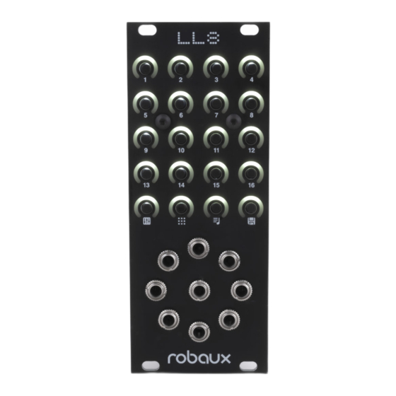
- Page 1 Assembly Guide...
- Page 2 These assembly instructions will help you build your Robaux LL8. All necessary components are included in this kit. You will need the following tools: soldering iron, wire cutter and solder. Also a desoldering pump and a screwdriver. Read the instructions carefully and follow the steps in the cor- rect order.
-
Page 3: Tact Switch
Tact Switch Now insert the 20 tact switches and solder them to the board. Attention! The switches must be soldered directly to the board, there must be no space between the board and the switch. LEDs Solder the 20 LEDs so that the edge of the LEDs lies straight on the housing of the tact switch. - Page 4 Header Turn the board over and solder the two headers as shown in the picture. Standoff Now screw the bolts into the board. The longer male bolt is inserted through the board from below and screwed to the smaller female bolt from above.
- Page 5 Frame Now carefully plug the frame onto the board. Thonkiconn Plug the nine Thonkiconn so- ckets onto the board as shown in the picture. Attention! Do not solder them yet.
- Page 6 Skrews Now place the panel on the board and screw it with the two black screws. Knurled Nuts Use the knurled nuts to tighten the jacks on the front panel. When everything is screwed tight and all components are aligned, you can solder the sockets.
- Page 7 Diodes Now pick up the mainboard and solder the ten diodes to the board as shown in the picture. Please pay attention to the polarity! Resistor 1K Now solder the 1K resistors to the board. You can recognize the resistors by their color code brown, black, red, gold.
- Page 8 Resistor 100 Now solder the five 100 resistors to the board. You can recognize the resistors by their color code brown, black, brown, gold. Resistor 10K Now solder the five 10K resistors to the board. You can recognize the resistors by their color code brown, black, orange, gold.
- Page 9 Crystal Now solder the 16MHz crystal as shown in the picture. Capacitor 220 Now solder the two 220 capa- citors to the board as shown in the picture.
- Page 10 Capacitor 104 Now solder the 104 capacitor to the board as shown in the picture. Rectifier Now it‘s time for the rectifer. Solder this to the PCB as shown in the picture. Note that the - and + symbols on the board match the symbols on the rectifer.
- Page 11 IC Socket 16 Solder the IC socket 16 to the board. It is easiest to solder first only the outer pins and then the remaining ones. IC Socket 28 Solder the IC socket 28 to the board. It is easiest to solder first only the outer pins and then the remaining ones.
- Page 12 Pins Place and solder the Male Pin Headers as shown in the picture. It is the shorter pins of the pin header that you are soldering. Capacitors Now solder the two Electrolytic Capacitors to the board as shown in the picture. Please pay attention to the polarity of the Capacitors.
-
Page 13: Power Socket
Step Down Now solder the step-down adapter as shown in the picture. Power Socket Solder the power connector to the board. -
Page 14: Shift Register
Shift Register Now plug the Shift Register onto the socket. Make sure that the IC points to the left. ATMega Now plug the ATMega onto the socket. Make sure that the IC points to the right. - Page 15 Pins Take the control board and put the pins on the headers. Skrew Now plug the main board onto the pin headers. First screw the two boards together and then solder the pin headers. And that‘s it, your Lil Eight is ready!
Need help?
Do you have a question about the LL8 and is the answer not in the manual?
Questions and answers