Table of Contents
Advertisement
Quick Links
Emergency Lighting Inverter
EXT Series(Outdoor)
Single-Phase, 2.1KW ~ 17KW
Installation and Operation Manual
Perfect Power System
Phone: (800)-786-6915
FAX no: (800)-246-2346
Technical Assistance: service@800pwrsrvc.com
Document No.: 725-MAN, Rev.B
All trademarks and registered trademarks are the property of their respective owners.
Due to continuous product improvement, this document is subject to change without prior notice
Advertisement
Table of Contents
Troubleshooting

Related Manuals for Perfect power systems EXT Series

Summary of Contents for Perfect power systems EXT Series
- Page 1 Emergency Lighting Inverter EXT Series(Outdoor) Single-Phase, 2.1KW ~ 17KW Installation and Operation Manual Perfect Power System Phone: (800)-786-6915 FAX no: (800)-246-2346 Technical Assistance: service@800pwrsrvc.com Document No.: 725-MAN, Rev.B All trademarks and registered trademarks are the property of their respective owners.
- Page 2 Notice of Rights This document contains proprietary and confidential information of the manufacturer. No part of this manual may be reproduced, copied, translated or transmitted, in any form or by any means, without the prior written permission of the company. Notice of Liability Information provided in this manual is intended to be accurate and reliable.
-
Page 3: Table Of Contents
Table of Contents Table of Contents......................3 Introduction ........................5 Scope and Audience........................5 Safety and Warnings ........................5 Warranty Registration and Warranty Certificate Request ............5 Service ............................5 Chapter 1. Safety ....................6 Chapter 2. Overview ..................... 10 2.1 Product Description ...................... - Page 4 Table of Contents Chapter 8. Specifications ..................60 APPENDIX A - Battery Connections ................65 APPENDIX B - Options ....................73 B.2 Internal Manual Bypass Switch (Make Before Break) ............74 B.3 Form “C” N/O Contacts for Alarms ..................74 B.4 Dry Contact, N/O or N/C Contact with Isolated Common ..........
-
Page 5: Introduction
Introduction This manual tells you how to install, start and operate your unit and lets you know how to get more information for special situations, and provide contact information Scope and Audience This guide is intended to be used as a reference for users responsible for installing, operating, and maintaining this equipment. -
Page 6: Chapter 1. Safety
Chapter 1. Safety This chapter contains safety precautions to observe when operating or servicing electrical equipment. The symbols shown are used extensively throughout this manual. Always heed these precautions because they are essential to the safe operation and servicing of this product. 725-MAN Rev B Page 6 of 89... - Page 7 Safety DANGER: This Equipment is intended to be permanently connected. Only factory-trained or authorized personnel should attempt to install or repair the unit or its batteries system. Improper installation has proven to be the single most significant cause of start-up problems.
- Page 8 Safety DANGER: All power to the unit must be locked and tagged "off" before performing any service or work on the unit. failure to do so could result in electrocution. DANGER: In case of fire involving electrical equipment, only carbon dioxide fire extinguishers, or those approved for use on electrical equipment, should be used.
- Page 9 Safety DANGER: Lead-acid batteries contain hazardous materials. Batteries must be handled, transported, and recycled or discarded in accordance with federal, state, and local regulations. Because lead is a toxic substance, lead-acid batteries should be recycled rather than discarded. Do not dispose of batteries in a fire, the batteries may explode. Do not open or mutilate the batteries.
-
Page 10: Chapter 2. Overview
Chapter 2. Overview This chapter provides an overview of the Single-Phase Lighting Inverter Standard Series. 2.1 Product Description The Harsh Environment Single-Phase Lighting Inverter is manufactured to provide critical power for lighting during a power outage. The Lighting Inverter meets or exceeds the life safety codes of UL924 and UL1778. -
Page 11: Product Features
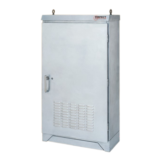
Overview Figure 2-1. Series Single-Phase Lighting Inverter Cabinets Outdoor Series 2.2 Product Features Item Components Function Input Contactor K1 The input contactor is multifunctional. First, it provides connections for the input power to the unit. Secondly, the contactor disconnects the input line when an outage occurs so that there is no back feeding of power into the power line. - Page 12 Overview Item Components Function Power Board Assembly with IGBTs The Power Board is bolted onto the IGBT (Insulated Gate Bipolar Transistor) blocks that are mounted on a heat sink. The complete Heat Sink Assembly with IGBTs and Power Board is replaceable as a single part. This FRU (Field Replaceable Assembly) converts all the power, i.e.
-
Page 13: Chapter 3. Hardware Overview
Chapter 3. Hardware Overview This chapter provides an overview of the system hardware. It includes a description of the system’s theory of operation. 725-MAN Rev B Page 13 of 89... -
Page 14: Key Components
Hardware Overview 3.2 Key Components Figure 3-1 shows the key system components and Table 3-1 describes them. Figure 3-1 Key Components for all other units (typical) 725-MAN Rev B Page 14 of 89... - Page 15 Hardware Overview Table 3-1. Key Components description Callout Component Name Description Power board (A1) The power board is bolted onto the Insulated Gate Bipolar Transistor (IGBT) blocks mounted on a heat sink. The complete heat sink assembly with IGBTs and power board is a single Field Replaceable Unit (FRU) that converts all the power: Input AC power converted to DC bus...
- Page 16 Hardware Overview Callout Component Name Description Control transformer fuse (F1) Behind panel Control transformer over current protection Fan fuse (F2), behind panel Fan overcurrent protection. Fan(s) Provides system cooling. Output isolation transformer T1, as required Provides isolation between the inverter and protected output.
-
Page 17: Functional Description (Typical)
Hardware Overview 3.3 Functional Description (Typical) Figure 3-2 shows the major blocks within the system and the sections following the figure describe them. Figure 3-2. Major System Blocks 3.3.1 Inverter The inverter accepts the available DC power from the rectifier or the battery banks and converts it to AC power for the critical load. - Page 18 Hardware Overview 3.3.3 Output Transformer The output transformer is used for multiple output voltage units only. It performs the following functions: It provides excellent common mode and normal mode noise isolation of the load from the input or inverter power. It provides voltage transformation and tight regulation of the output voltage, while the system ...
-
Page 19: Theory Of Operation
Hardware Overview System efficiency increases by 2 to 4% depending on the model. Total power loss is reduced. The output AC voltage in the mode of operation follows proportionally to the input line voltage. The system supports two off-line inverter modes: A fast transferring version, with a quarter cycle (2.5 milliseconds). - Page 20 Hardware Overview drops below 16% of its nominal value and the facility power remains off, the system enters into alert mode. 3.4.3 UPS Alert The system controller issues an ALERT message on the LCD display panel if any of the following conditions occurs: Internal failure ...
-
Page 21: Chapter 4. Installation
Chapter 4. Installation This chapter describes how to install the system. It includes pre-installation information along with guidelines for storing the system for future use. 4.1 Delivery Space Requirements Verify that the delivery area, the destination, and the path between them meet the standard delivery clearance and weight requirements of the system. - Page 22 Installation Figure 4-1. 3KVA/KW To 5KVA/KW Cabinet 725-MAN Rev B Page 22 of 89...
- Page 23 Installation Note: Use conduit plates only for drilling. (Do not discard the conduit plate) Figure 4-2. 7.5KVA – 17KW Cabinet Note: Use conduit plates only for drilling. (Do not discard the conduit plate) 725-MAN Rev B Page 23 of 89...
-
Page 24: Site Considerations
Installation Note: After final installation of the unit the 2 brackets can be turned upside down by using (7/32" Tamper-Resistant Hex) tool 4.2 Site Considerations Planning the proper location and layout of the system prior to installing it is essential for successful operation. - Page 25 Installation The system is less than 6 square feet. All servicing is performed through the front of the unit; therefore, leave sufficient room in the front of the unit for service access. The following precautions will help you plan an acceptable operating environment for the system: Select a flat location that is clean, with no dust or exposure to direct sunlight or vibrations.
- Page 26 Installation 4.2.1 Recommended Input / Output Protective Device Ratings, BTU/HR, & Floor Loading Table 4.1 Unit *BTU/HR Unit Max. Input *BTU/HR Cabinet Unit Weight Double Floor Batt. Batt. Dimensions Rating Input Outpu Circuit Fast (including Loading Conversio W x H x D KVA / Volt.
- Page 27 Installation Unit *BTU/HR Unit Max. Input *BTU/HR Cabinet Unit Weight Double Floor Batt. Batt. Dimensions Rating Input Outpu Circuit Fast (including Loading Conversio W x H x D KVA / Volt. t Volt. Breaker Transfer Batteries) Volt Disch LB/SQFT lbs. Inches (Amps) (Typical)
-
Page 28: Delivery And Handling
Installation 4.2.2 Operating Environment The location you choose for installation should confirm to the following conditions. Table 4-2. Inverter Environmental Specifications Inverter Environment Description\ Operating Temperature: -20° to +50°C (-4° to 122°F) with optional heater Battery compartment to be kept at battery operating temperature Altitude: Up to 13000 ft (3,962 meters) Relative Humidity:... - Page 29 Installation damage on the receiving document before signing for receipt of the equipment. Damage claims should be filed directly with the carrier. Thoroughly inspect each battery for any signs of damage. If there is any damage, reject the shipment services@800pwrsrvc.com and notify the manufacturer by email .
- Page 30 Installation 1. Open all cartons. 2. Compare the items received to the packing list. If an item is missing or damaged, contact your place of purchase. 3. Remove all packing materials, envelopes, and boxes from the cartons. Please keep all packing materials and cartons in case you need to transport or ship the unit.
- Page 31 Installation Figure 4-4 All other systems Note: To prevent moisture entering the cabinet all openings at the bottom must be weatherproof after installation. For all cable entries to the unit: 1. Use conduit plates only for drilling. (Do not discard the conduit plate) 2.
- Page 32 Installation 4.3.6 Electrical Connections The following sections describe how to perform the electrical connections. In these sections, “TB” refers to terminal block. Before making electrical connections, observe the following: DANGER: Verify that all customer-supplied wiring is de-energized before performing any electrical work.
- Page 33 Installation Figure 4-6 Single Output Voltage Connection with Optional Main Input/Output and Auxiliary Breakers (Typical) 725-MAN Rev B Page 33 of 89...
- Page 34 Installation Figure 4-7 Dual Output Voltage Connection with Optional Main Input/Output and Auxiliary Breakers (Typical) 725-MAN Rev B Page 34 of 89...
- Page 35 Installation Figure 4-8 Input and Output Connection Single Output Voltage (120V, 240V, 277V, 208V) Table 4.4 Input and Output Connection Single Output Voltage Input Connection Output Connection Ground Lug Ground Lug Volt Volt Input Output GND (IN) GND (OUT) GND (IN) GND (OUT) GND (IN) GND (OUT)
- Page 36 Installation 4-9 Input and Output Connection Dual Output Voltage Table 4.5 Input and Output Connection Dual Output Voltage Input Connection Output Connection Ground Lug Ground Lug Volt Volt Input Output 120V GND (IN) 120V GND (OUT) 208V GND (IN) 240V 240V GND (IN) 120V...
-
Page 37: Storing The System
Installation Caution: Ensure that the DWG NO of the system matches the DWG NO on the nameplate. See the sample nameplate Figure 4-10. Sample Nameplate 4.3.7 Optional Remote Signaling Connections The Single-Phase Lighting Inverter includes optional dry contacts relay for remote signaling. 4.3.7.1 Form “C”... - Page 38 Installation Specification Description Storage Temperature: -20° to 70°C (-4° to 158°F) Relative humidity: 0% to 95% (non-condensing) Note: After unpacking and before turn-on: use plastic cover provided in the pouch on the front door to cover the unit during installation and while waiting for turn on, to prevent dust, construction debris and any other foreign object entering the unit.
-
Page 39: Chapter 5. Operation
Chapter 5. Operation This chapter describes how to operate the unit. 5.1 Starting the Unit for the First Time 5.1.1 Pre-start up The unit’s batteries are shipped directly from manufacturer to ensure brand new batteries and allow an opportunity for the installing contractor to schedule their arrival when they are ready to commission the system. - Page 40 Operation 5.1.2 Preparation of Batteries a. Ensure proper number of batteries are delivered with your order. Verify quantity against battery drawing located in the inner door pouch. b. Place battery ID (Number) labels on each battery, refer to Battery Installation and Connection Instruction: Document No.
- Page 41 Operation 5.1.4 Turning Off the Unit There may be times when you need to turn off the unit, such as for planned maintenance. To turn off the unit, perform this procedure in the following order: 1. Turn off the output breakers. 2.
-
Page 42: Chapter 6. Maintenance
Chapter 6. Maintenance This chapter describes how to maintain the system. 6.1 Safety Precautions Observe the following safety precautions when performing maintenance on the unit. DANGER: Read and understand this section thoroughly before performing any maintenance work on or around the UPS. Read the battery manufacturer's manual and material safety data sheets before working on or near the batteries. -
Page 43: Preventative Maintenance
Maintenance DANGER: Observe all battery safety precautions during installation or service of the UPS or batteries. Even with the battery circuit breaker in the off position, the danger of electrocution may still be present. The battery power to the unit must be locked and tagged "off"... - Page 44 Maintenance DANGER: The battery circuit breaker operates at the rated battery voltages at all times. A tripped battery circuit breaker indicates a serious problem that may result in serious injury or damage to the equipment. Determine the cause and take appropriate action as necessary.
- Page 45 Maintenance Caution: Lead-acid batteries can present a risk of fire because they generate hydrogen gas. The following safety procedures must be followed: Do not smoke when near batteries. Do not cause flame or sparks in battery areas. Discharge static electricity from your body before touching batteries by first touching ...
-
Page 46: Fru Replacement
Maintenance Use the correct torque tool to tighten the terminal bolts shown on the drawings on the battery cabinet. Use all hardware provided with the batteries. Caution: Torque all connections in accordance with specified values provided. Failure to do so can create an unsafe condition or fire hazard. 6.2.6 Air Filters Air filters must be replaced every 3 months or sooner depending on environment condition. - Page 47 Maintenance Item Description Designator Power board (A1) Heat sink assembly Bypass static switch (PB2) Inverter static switch (PB1) Power board Bypass static switch Inverter static switch Input/output/battery terminal block for customer use TB1, TB2, TB3 Input choke L1, L3 Output choke Dc choke The Frequency Noise Filter Capacitors for output Power C1, C2, C3...
- Page 48 Maintenance 6.3.1 Replacing the Heatsink Assembly To replace Heatsink Assembly: Disconnect wires: A4-P1 PB2-1 PB2-2 A3-P1 PB1-2 PB2-2 Ribbon Cable TB4-B (All wires) P1 (when fast transfer option is used) 1. Remove heatsink (2) mounting screws and slide the assembly out 2.
- Page 49 Maintenance Figure 6-2. Heatsink Assembly (all others) 725-MAN Rev B Page 49 of 89...
- Page 50 Maintenance 6.3.2 Replacing the Control Board (1625-288-XX) Standard The control board is located on the inside right door for up to 5kw units and on the swing-out panel on top front for all others. Figure 6-3. Control Board (standard) 725-MAN Rev B Page 50 of 89...
- Page 51 Maintenance 6.3.3 Replacing the Control Board (1625-344-XX) Event Log option This control board is located on the inside right door for up to 5kw units and on the swing-out panel on top front for all others when the event log option is used. Figure 6-4.
- Page 52 Maintenance 6.3.4 Replacing the (1625-405,406,407-XX) Fast Transfer option This control board is located on the inside right door when fast transfer option is used Figure 6-5. Fast Transfer option 6.3.5 All Other Parts Verify that the cables are marked before disconnecting. Replace the defective part with the new part.
-
Page 53: Calling For Service
Maintenance 6.4 Calling for Service Call for service if you encounter any of the following conditions: Repeated start-up attempts are unsuccessful. A UPS fault occurs that cannot be cleared. Normal operation of the critical load repeatedly causes an overload condition. This is not a UPS ... -
Page 54: Chapter 7. Troubleshooting
Chapter 7. Troubleshooting This chapter describes how to use the LCD display panel to perform troubleshooting suggestions. 725-MAN Rev B Page 54 of 89... -
Page 55: Reset Instructions
Troubleshooting 7.1 Reset Instructions Due to facility and/or incoming power abnormalities, prior to initiating a service call please attempt a System “RESET” by following the Reset Instructions described below: Instructions: 1. Turn off all system output breakers. 2. Turn off the systems battery breaker. 3. - Page 56 Troubleshooting Symptoms Case Causes Action Description LCD Display Attempt to turn on Connector P3 has Unplug P3, verify voltages are UPS ALERT @ ## KW and unit remains in bad connection present across pin 1 & 2 and 3 & INPUT BAD @ CHRG OFF BYPASS_ and LCD...
-
Page 57: Using The Lcd Display Panel
Troubleshooting 7.3 Using the LCD Display Panel All units have the screens in Figure 7-2 and Figure 7-3. Units equipped with the optional output transformer also have the screen in Figure 7-4. All screens are updated continuously to provide you with up-to-the-minute status information. - Page 58 Troubleshooting Table 7-1. Description of Default Screen 1 Line Message Description UPS NORMAL @ 15 KVA 15 KVA indicates the KVA rating. STAND BY or NORMAL = normal operating modes. STAND BY ALARM FAILURE = UPS alarm condition. FAILURE = unit failed or persistent alarm condition. Shut off the system and wait for the LCD to go dark, then restart the unit.
- Page 59 Troubleshooting Line Description Shows the battery voltage. (+) = current in Amps indicates charging Amps. (-) = discharging Amps. 7.3.3 Default Screen 3 If the optional output transformer is installed, the following screen shows the multiple output voltages. Figure 7-4 shows the first default screen. OUTPUT: 120V @ OUTPUT: 208V @ OUTPUT: 277V @...
-
Page 60: Chapter 8. Specifications
Chapter 8. Specifications This chapter provides the general specification of the system 725-MAN Rev B Page 60 of 89... - Page 61 Specifications Typical Specifications (Input / Output Current) 725-MAN Rev B Page 61 of 89...
- Page 62 Specifications Specification (General) Input Voltage Regulation +10% -15% Frequency (Hz) 60 Hz ±3% Power factor 0.98 to 1.0 (Typical) Overcurrent protection Electronic / Circuit Breaker (Optional) Number of wires 2 Wires plus Ground Power connection Hard Wired (Terminal Block) Output Voltage (vac) Single Phase, 120/208/240/277 VAC Voltage Regulation...
- Page 63 Specifications Battery type Sealed, Maintenance-Free, AGM, VRLA type Unit Rating (KW) 2.1 / 3 3.5 / 5 5.25 / 7.5 7 / 10 8.75 / 12.5 10.5 / 15 14 / 17 Nominal dc voltage 96 VDC 120 VDC 144 VDC 120 VDC 192 VDC 192 VDC 192 VDC...
- Page 64 Specifications Cable entry Bottom only Mounting Four (4) mounting holes are provided for anchoring to floor, Hardware to be supplied by others Specification subject to change without prior notifications 725-MAN Rev B Page 64 of 89...
-
Page 65: Appendix A - Battery Connections
APPENDIX A - BATTERY CONNECTIONS This chapter shows typical battery connection diagrams. The figures are provided for electrical connection only and do not necessarily match the actual battery layout in your unit. The arrangement may be different from the figures. Refer to your system battery connection diagram provided inside front door packet. - Page 66 Battery Connections 96-Volt Nominal DC Voltage, 1 String of 8 Battery in 39” cabinet (Typical) 725-MAN Rev B Page 66 of 89...
- Page 67 Battery Connections 120-Volt Nominal DC Voltage, 1 String of 10 Battery in 39” cabinet (Typical) 725-MAN Rev B Page 67 of 89...
- Page 68 Battery Connections 120-Volt Nominal DC Voltage, 1 String of 10 Battery in 51” cabinet (Typical) 725-MAN Rev B Page 68 of 89...
- Page 69 Battery Connections 144-Volt Nominal DC Voltage 1 String of 12 Battery in 51” cabinet (Typical) 725-MAN Rev B Page 69 of 89...
- Page 70 Battery Connections 192-Volt Nominal DC Voltage, 1 String of 16 Batteries in 51” cabinet (Typical) 725-MAN Rev B Page 70 of 89...
- Page 71 Battery Connections 192-Volt Nominal DC Voltage, 2 String of 16 Batteries in 51” cabinet (Typical) 725-MAN Rev B Page 71 of 89...
- Page 72 Battery Connections 240-Volt Nominal DC Voltage, 1 String of 20 Batteries in 51” cabinet (Typical) 725-MAN Rev B Page 72 of 89...
-
Page 73: Appendix B - Options
APPENDIX B - OPTIONS This appendix provides detailed information about the options available for the Single-Phase Lighting Inverter. 725-MAN Rev B Page 73 of 89... -
Page 74: Internal Manual Bypass Switch (Make Before Break)
Options B.2 Internal Manual Bypass Switch (Make Before Break) Internal Manual Maintenance Bypass Switch is a (3) position “UPS”, “SBS” and “BYPASS” rotary switch, when set to “BYPASS” provides power directly from UPS main input feed to the load which ensures continuous power to critical load without interruption. -
Page 75: Battery Breaker Alarm
Options Terminal Number Signal Description TB-18-3 (N/C) TB-18-4 (COM) ON BYPASS When the unit transfers the load to static by-pass. TB-18-5 (N/O) TB-18-6 (N/C) TB-18-7 (COM) LOW BATTERY When the unit is on battery operation and the batteries approach inadmissible discharge status. TB-18-8 (N/O) TB-18-9 (N/C) TB-18-10 (COM) - Page 76 Options with an external transformer. A wraparound bypass switch can be used with systems without any “built in secondary distribution circuit breaker” within the unit. Enclosure Dimensions Dimension (inches) Voltage Class 55 AMP 600V 16.75 110 AMP 600V 16.75 175 AMP 600V 18.5 18.5...
- Page 77 Options Maintenance Bypass Switch Wiring Diagram (Typical) To install the maintenance bypass switch Always allow front access to the MBS box for maintenance and servicing. Electrical codes require that the maintenance bypass switch box be installed with no less than 3 feet at the front of the cabinet.
-
Page 78: Audio Alarms With Silence Switch
Options B.7 Audio Alarms with Silence Switch The audio alarms with silence switch provides an audible warning signal, acknowledge, and reset for Input Fail, On Bypass, Inverter On, Low Battery and Summary Alarm for any of the foregoing alarm conditions. B.8 Remote Status Panel The remote UPS status panel is a console mount style box that can also be wall mounted. -
Page 79: Transient Voltage Surge Suppressor (Tvss)
Options B.9 Transient Voltage Surge Suppressor (TVSS) The TVSS contains energy-absorbing components designed for specific line configurations. If protection components become damaged by absorbed transients, the device shows a reserve flag that indicates a need for replacement. The unit remains operational, but without surge protection. B.10 Offline Inverter Operation The offline inverter operation consists of a slow transfer unit and a fast transfer unit. -
Page 80: Global Monitoring Systems (Gms)
Options Green = Input OK or inverter is ON. Yellow = On battery, or on bypass. Red = Low battery or summary alarm. Power Flow Mimic B.15 Global Monitoring Systems (GMS) 4. Monitoring, Local On UPS – Event log The control and monitoring PCBA collect event data and displays up to 100 of the most recent date- and time-stamped events. - Page 81 Options LOG – press to display the event log. All stored events scroll continuously on display. Press this key again to redisplay the main menu. Example of Logged Events FREEZE = press to freeze the default monitoring and alarms screen temporarily. Press this key ...
- Page 82 Options Example of System Info Screen RESET and INFO = press these keys at the same time to clear the display. Monitoring, Local On UPS - Aux CBs Trip Monitor Trip signals from the breakers are displayed on the circuit breaker trip screen. The circuit breaker is a part of default monitoring and alarm display that scrolls continuously when the unit is in operation.
-
Page 83: Local Monitoring Via Pc With Rs-232
Options B.15.1 Local Monitoring via PC with RS-232 The local monitoring via PC with RS-232 option requires a PC and LabView monitoring software. The software is provided on a disc that installs easily on any Windows operating system. An attached cable of a specified length plugs into a PC serial port and connector J6 on the Control Board located inside right door. -
Page 84: Simple Network Management Protocol
Options B.16 Simple Network Management Protocol This option consists of a basic SNMP NetAgent mini-external device as an advanced SNMP NetAgent device. Example of Basic NetAgent Mini-external Device Example of Advanced NetAgent Device This option is available in the following offerings: Basic NetAgent SNMP with WI-FI HUB application ... -
Page 85: Battery Thermal Runaway Control
Options B.17 Battery Thermal Runaway Control This option provides protection in case of over-temperature condition in the battery compartment. If such a condition occurs, this option shuts off the charger. Charging resumes when the temperature returns to normal. A dry contact (N/O, N/C) relay interface is provided for this option for user interface per following: 725-MAN Rev B Page 85 of 89... -
Page 86: Heater Strip With Adjustable Thermostat
Options Terminal Number Signal Description TB121-1 N/C contact that opens when the critical temperature has reached TB121-2 Common TB121-3 N/O contact that closes when the critical temperature has reached Refer to APPENDIX B- Figure 1 for terminal block location B.18 Heater Strip with Adjustable Thermostat The option provides flexibility of installing a heater with thermostat for adjusting temperature range to control harsh environment ambient temperature B.19 Battery String Monitoring (Wireless) - Page 87 Options APPENDIX B- Figure 1 (Communications and Alarm Signaling Interfaces 725-MAN Rev B Page 87 of 89...
-
Page 88: Index
Index Alarm, 20 Alarms, 20 LCD display panel, 57 Alerts, 20 Audience, 5 Maintaining batteries, 43 Maintenance, 42, 60 Battery preventative, 43 connections, 36, 65 Maintenance agreements, 53 maintaining, 43 Modes, 19 recharging, 38 Monitoring, Local On UPS - Aux CBs Trip Monitor, 82 terminals, 46 Monitoring, Local On UPS –... - Page 89 Options System blocks, 17 Safety, 6 Service, 5, 53 Shipment Testing the UPS, 43 inspecting, 28 Theory of operation, 19 unpacking, 29 Turning off the unit, 41 Site considerations, 24 Specifications, 64 Standby mode, 19 Starting the unit Unpacking, 29 after planned shutdown, 41 Start-up services, 53 alarm, 20...