Table of Contents
Advertisement
Quick Links
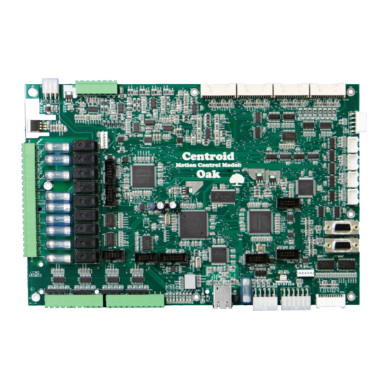
Centroid OAK CNC Control Installation Manual
CNC CPU combination with AC Servo drive interface w/ built-in PLC and Spindle control
www.centroidcnc.com
Centroid_Oak_install_manual.pdf rev 4-10-15 Copyright © 2015 CENTROID
OAK CNC control
Introduction and Discussion
What's Included
Bench Testing Hardware Setup
Windows and CNC software install
Electrical Cabinet Installation
Final CNC Software Configuration
4
5
8
14
19
Bench Test
24
38
53
Appendices
Advertisement
Table of Contents

Related Manuals for Centroid OAK

Summary of Contents for Centroid OAK
- Page 1 OAK CNC control Centroid OAK CNC Control Installation Manual CNC CPU combination with AC Servo drive interface w/ built-in PLC and Spindle control Introduction and Discussion What’s Included Bench Testing Hardware Setup Windows and CNC software install Bench Test Electrical Cabinet Installation...
-
Page 4: Table Of Contents
5.5 Wiring Limit Switches............................31 5.6 Wiring Lube Pump.............................32 5.7 Wiring Coolant Pump............................33 5.8 Wiring Spindle..............................34 5.9 Wiring 3rd Party Servo Amplifiers to the Oak Board..................37 Chapter 6 – Final Software Configuration.........38 6.1 Programing your Third Party Drive........................38 6.2 Confirm Encoder Communication........................40 Page 2 of 72 T:\_Docs working\Oak Board Manual\Oakboard install manual V2 4-10-15.odt... - Page 5 Axes don't move - No Error or Fault displayed......................53 Full Power Without Motion, Position Errors and SV_STALL Errors..............54 Motor Behaving Unexpectedly..........................54 Appendix B: Technical Information...........55 Appendix C: 3rd Party Drive Cable Information.......69 Page 3 of 72 T:\_Docs working\Oak Board Manual\Oakboard install manual V2 4-10-15.odt...
-
Page 6: Introduction
EFORE EGIN Installing the Centroid CNC11 based Oak Board system is a straight forward process if the directions are followed. Before getting started, please take the time to familiarize yourself with the schematics, manuals and installation instructions. While doing the installation, it is very important that you follow the instructions in order and that you follow them exactly. -
Page 7: Chapter 1 - What's Included
Output Cable 1 Oak Board 2 Power Supply SIPs The following components are included with your Oak Board: 1. Oak Board ........................Part Number 13126 2. Power supply........................Part Number 7135 3. Power supply Output cable..................... Part Number 13106 4. Seven position terminal block................... Part Number 2611 5. -
Page 8: Cables
Yaskawa Sigma I, II, V 13134 Flying Lead 13133 6. Console Extension Cable (extensions available)............Part Number 11028 (6 ft) ◦ Includes Jog, MPG, Ethernet. Console Power, and E-stop cables Page 6 of 72 1.2 Cables T:\_Docs working\Oak Board Manual\Oakboard install manual V2 4-10-15.odt... -
Page 9: Overview
1.3 O VERVIEW Page 7 of 72 1.3 Overview T:\_Docs working\Oak Board Manual\Oakboard install manual V2 4-10-15.odt... -
Page 10: Chapter 2 - Connecting Components For A Bench Test
• the recommended and easiest method. A PC with an internet connection, or a Centroid console unit (comes with CNC11 already installed). • Note: The PC must meet the specifications listed in Technical Bulletin 273, which can be found here: (http://www.centroidcnc.com/dealersupport/tech_bulletins/uploads/273.pdf) -
Page 11: Bench Test - Power Supply Configuration
Connect Oak Board to the power supply: Follow the instructions below. 1) Connect the supplied cables to the Mean Well power supply and the plug labeled Power on the Oak board. Connect position 1 and 2 from H1 on the Oak Board to V4 and COM respectively. -
Page 12: Bench Test - Communication Configuration
Connect the Shielded Ethernet Cable: Connect a shielded Ethernet cable from your Oak Board to the PC. A shielded Ethernet cable will have a metal clip around the RJ-45 connector as shown on the cable on the right in Figure •... -
Page 13: Bench Test - Connecting Accessories
– C ENCH ONNECTING CCESSORIES Connect Any Accessories: Connect optional accessories If a Jog Panel/Pendant or MPG was ordered, please connect it to the Oak Board as seen in Figures 2.4.1 and 2.4.2. • Figure 2.4.1 Jog Pendant Figure 2.4.2 Page 11 of 72 2.4 Bench Test –... -
Page 14: Bench Test - Powering On & Verifying Led States
Before powering on, verify that nothing metallic can touch the circuit boards and cause a short. Make sure all wiring is firmly in place. Switch the outlet strip on: Powering the Oak Board and any accessories. Oak Board Status LED states: After 15-30 seconds the status LED's should all be solid on except for DEBUG, which should flash once per second, and DF, which doesn't turn on until the software is installed. - Page 15 PLC OK LED out processor section load hasn't booted up LED1 display flashing with decimal An error condition has See the "LED1 Error Codes" section in Oak point lit been detected Manual for details on the error LED1 Display Figure 2.5.2...
-
Page 16: Chapter 3 - Software Installation
OFTWARE INSTALLATION 1. If a console unit or computer was purchased from Centroid, it already comes with Windows properly configured and the CNC11 software already installed. If using your own computer, it must meet the prerequisites listed in TB 273 posted here: (http://www.centroidcnc.com/dealersupport/tech_bulletins/uploads/273.pdf) -
Page 17: Cnc 11 Software Installation
Enter or extract the cnc11_win7_latest folder, you will see the installation folder inside. The installation folder in this example is called centroid-cnc11-v314. The “v314” signifies the CNC11 version, yours may be newer, do not use a version lower than v314 with the Oak Board. Copy this to the desktop. Figure 3.2.1 Copy to desktop 4. - Page 18 Check the “Automatically start the WinPcap at boot” box when prompted (not shown). Figure 3.2.5 Figure 3.2.6 Software installation Installation complete 8. Click “Next” to continue: After the WinPcap installation has finished, click “Next.” Page 16 of 72 3.2 CNC 11 Software Installation T:\_Docs working\Oak Board Manual\Oakboard install manual V2 4-10-15.odt...
- Page 19 Disconnect all ethernet cables from the PC except for the one connecting to the Oak Board. The Oak Board should be powered If you see multiple options, return to step 4 and make sure only the Oak Board is plugged into the ethernet ports. Note: Your IP address will differ from those shown in the picture.
- Page 20 Note: the plc installer can be found in the same folder as setup, the download link is in the beginning of this section. Figure 3.2.9 PLC installer 11. Click “Finish” to complete CNC11 software installation. 12. Power off everything and restart. Page 18 of 72 3.2 CNC 11 Software Installation T:\_Docs working\Oak Board Manual\Oakboard install manual V2 4-10-15.odt...
-
Page 21: Chapter 4 - Configuring For A Bench Test
In general, when using CNC11, you can always go back one menu level by pressing the escape key (ESC). Tapping escape multiple times from any menu will take you back to the main menu. Page 19 of 72 4.1 Bench Test – CNC11 Software Configuration T:\_Docs working\Oak Board Manual\Oakboard install manual V2 4-10-15.odt... - Page 22 Select Jog Panel Required in the Control Configuration and press the space bar to change to No. Press F10 Save. Figure 4.1.4 Disabling jog panel Page 20 of 72 4.1 Bench Test – CNC11 Software Configuration T:\_Docs working\Oak Board Manual\Oakboard install manual V2 4-10-15.odt...
- Page 23 Under Label all axes should be set to N to disable the axis for bench testing as seen in Figure 4.1.6. 7. Save: Press F10 Save. Figure 4.1.6 Labeling the axes Page 21 of 72 4.1 Bench Test – CNC11 Software Configuration T:\_Docs working\Oak Board Manual\Oakboard install manual V2 4-10-15.odt...
- Page 24 Remember to cycle the E-Stop to clear the fault and press F3 MDI to test if it is cleared. Figure 4.1.9 MDI Command Mode Figure 4.1.10 Faults detected Page 22 of 72 4.1 Bench Test – CNC11 Software Configuration T:\_Docs working\Oak Board Manual\Oakboard install manual V2 4-10-15.odt...
- Page 25 Bench Testing Completed. Power off and disconnect the components. At this point it is confirmed that the Oak Board powers up, the parameters are set correctly, and the spindle voltage works. Page 23 of 72 4.1 Bench Test – CNC11 Software Configuration...
-
Page 26: Chapter 5 - Electrical Cabinet Wiring
NTRODUCTION TO LECTRICAL ABINET IRING During cabinet wiring it is important that you follow the schematic provided by Centroid. Decide on a layout for the cabinet and mount all the components. Figure 5.1.1 Sample Electrical Cabinet Layout Contactors and high voltage lines kept far away from sensitive electronics. - Page 27 For example, it would be bad practice to mount a contactor block or large transformer directly underneath the Oak Board. Keep the high-voltage AC power lines and motor power lines as far away from low voltage logic signals as practical.
- Page 28 A cutter cannot be Some strands are cut used to strip wires. because a cutter was used to strip. Figure 5.1.2 Common Wiring Problems Page 26 of 72 5.1 Introduction to Electrical Cabinet Wiring T:\_Docs working\Oak Board Manual\Oakboard install manual V2 4-10-15.odt...
-
Page 29: Electrically Configuring Inputs On The Oak Board
NPUTS ON THE OARD The inputs of the Oak Board can be configured for either 5, 12, or 24 volts DC. The input voltage is changed by changing the resistance of the SIP (single inline package) resistor. By default the Oak Board is supplied with SIPs for 24VDC installed. If you are using a voltage other than 24VDC, the SIPs need to be changed. - Page 30 Sourcing and Sinking All inputs on the Oak Board can be configured in banks of 4 for sourcing or sinking operation. Whether you will use sinking or sourcing depends on your devices. The inputs can use 5, 12 or 24 VDC, be sure to install the appropriate SIP resistor. The inputs are arranged in groups of four with a common shared by each input in a group.
-
Page 31: Install Major Components In Cabinet
The default inputs and outputs are listed in the following sections, if you have a custom PLC program they may be different. Wire power cable according to section 2.2 Must Use Shielded CAT5 or Better, Section 2.3 Page 29 of 72 5.3 Install Major Components in Cabinet T:\_Docs working\Oak Board Manual\Oakboard install manual V2 4-10-15.odt... -
Page 32: Wiring E-Stop
1. E-Stop Switch: Use a double pole single throw (DPST), normal closed, twist to release, emergency stop switch. Centroid part number #1009 used with #5934 is recommended, shown in figure 5.4.1. -
Page 33: Wiring Limit Switches
5. Confirm that all limit switches are green when nothing is tripped. Confirm that the corresponding input turns red when the switch is tripped. Page 31 of 72 5.5 Wiring Limit Switches T:\_Docs working\Oak Board Manual\Oakboard install manual V2 4-10-15.odt... -
Page 34: Wiring Lube Pump
Keep in mind that the Oak Board output relay is rated for up to 5 amps DC or 10 Amps AC. If your lube pump draws more current you will need to install a contactor (Centroid PART# 3959). -
Page 35: Wiring Coolant Pump
If you have mist, refer to the schematic for how to wire it. Figure 5.7.1 shows how to hook up a 3 phase Flood Pump. A Contactor (Centroid PART# 3959) is needed, shown in the figure. If you do not have access to 3 phase, refer to Tech Bulletin 163: (http://www.centroidcnc.com/dealersupport/tech_bulletins/uploads/163.pdf) -
Page 36: Wiring Spindle
Reversing Contactors: (logic connections shown in Figure 5.8.2, power connections in 5.8.3) • The 3 phase is connected to mechanically interlocked reversing contactors, controlled by outputs 7 and 8 on the Oak board. Use a Variable Frequency Drive (VFD): (shown in Figure 5.8.1) •... - Page 37 Figure 5.8.1 Sample VFD wiring with a GS2 Page 35 of 72 5.8 Wiring Spindle T:\_Docs working\Oak Board Manual\Oakboard install manual V2 4-10-15.odt...
- Page 38 Figure 5.8.2 Spindle Wiring Logic Figure 5.8.3 Spindle Wiring Power Page 36 of 72 5.8 Wiring Spindle T:\_Docs working\Oak Board Manual\Oakboard install manual V2 4-10-15.odt...
-
Page 39: Wiring 3Rd Party Servo Amplifiers To The Oak Board
13134 Flying Lead 13133 Plug the drives into the Oak Board where it is labeled Axis 1, Axis 2, Axis 3, etc. • ◦ If flying lead cables were purchased, please reference Appendix C for signal information. ◦ Appendix B has more information on all the cables Figure 5.9.1... -
Page 40: Chapter 6 - Final Software Configuration
If you have more than 4 axes, a lathe, or a unique drive configuration, refer to the CNC11 Operator's manual for more information about these parameters. 3. If you have a spindle encoder: be sure it is plugged into the Encoder 6 header on the Oak board Parameter 313 = 6... - Page 41 Make sure the cooling coefficients (parameters 25 – 28 and 236 – 239) are set to their default value of “0.68”. Press F10 to save when finished. Figure 6.1.3 Heating Coefficients Disabled Page 39 of 72 6.1 Programing your Third Party Drive T:\_Docs working\Oak Board Manual\Oakboard install manual V2 4-10-15.odt...
-
Page 42: Confirm Encoder Communication
Watching the “Abs Pos” field Rotating the shaft counter clockwise increase the value in the “Abs Pos” field of the PID Menu. Figure 6.2.2 Motor Faceplate Page 40 of 72 6.2 Confirm Encoder Communication T:\_Docs working\Oak Board Manual\Oakboard install manual V2 4-10-15.odt... -
Page 43: Clearing Software Faults
If you do not know the cause of the fault, confirm that all parameters are set as required in section 4.1 and 6.1, and that all inputs are in the correct state. Also, confirm your drive is wired correctly and configured to work with the Oak Board as set up in the drive's technical bulletin. -
Page 44: Motor Software Setup
DANGER: Use extreme caution the first time attempting to move the motor, they may move unpredictably as they have not yet been tuned. Keep a hand on the E-Stop. See Appendix A: Motor Behaving Unexpectedly for troubleshooting help. Page 42 of 72 6.4 Motor Software Setup T:\_Docs working\Oak Board Manual\Oakboard install manual V2 4-10-15.odt... - Page 45 +Z direction. Therefore, a +Z movement should move the tool up. Tool Moves in X+ direction Figure 6.4.2 Table verses tool movement Page 43 of 72 6.4 Motor Software Setup T:\_Docs working\Oak Board Manual\Oakboard install manual V2 4-10-15.odt...
- Page 46 2. Use the arrow keys to select the Dir Rev field for the axis that needs to be reversed. 3. Press the space bar to change it's state. Refer to Figure 6.4.3. Figure 6.4.3 Direction reversal Page 44 of 72 6.4 Motor Software Setup T:\_Docs working\Oak Board Manual\Oakboard install manual V2 4-10-15.odt...
-
Page 47: Configure Axes To Move Correct Distance
F1 Setup → F3 Config. Password 137. F2 Mach. → F2 Motor. Figure 6.5.1 Test Procedure Figure 6.5.2 Fine adjustment of motor revs/in or mm's/rev Page 45 of 72 6.5 Configure Axes to Move Correct Distance T:\_Docs working\Oak Board Manual\Oakboard install manual V2 4-10-15.odt... -
Page 48: Homing The Machine
(highlighted) Figure 6.6.1 Reversing limit switches in software 5) Repeat for the + and – limits for other axes. 6) Continue to step 2. Page 46 of 72 6.6 Homing the Machine T:\_Docs working\Oak Board Manual\Oakboard install manual V2 4-10-15.odt... - Page 49 Note: If the machine stops homing and the main menu says Warning: Machine not homed a limit switch was pressed in the wrong order and the machine faulted out. Refer to Technical Bulletin 22. Page 47 of 72 6.6 Homing the Machine T:\_Docs working\Oak Board Manual\Oakboard install manual V2 4-10-15.odt...
-
Page 50: Tune The Pid
◦ Ensure that parameter 256 is set to 2. ◦ Ensure The Axis Encoder Counts in the Centroid software are the same as the ones used for tuning. If using Velocity mode (Estun): follow TB 291, then follow the tuning guide in Tech Bulletin 234. -
Page 51: Backlash Compensation
The setup used is shown in figure 6.8.1. The screen to enter the corrected values is shown in figure 6.8.2, from the main screen press F1 Setup → F3 Config. Password 137. F2 Mach. → F2 Motor. Figure 6.8.1 Backlash Compensaton Figure 6.8.2 Entering Backlash Compensaton Page 49 of 72 6.8 Backlash Compensation T:\_Docs working\Oak Board Manual\Oakboard install manual V2 4-10-15.odt... -
Page 52: Software Travel Limits
The status screen will display a message such as “340 X- limit (#50001) cleared”. Jog another 0.1” (2.5mm) away from the limit switch. Continue to step 4. Page 50 of 72 6.9 Software Travel Limits T:\_Docs working\Oak Board Manual\Oakboard install manual V2 4-10-15.odt... - Page 53 Use the F3 MDI menu to issue a G-code that asks the software to move just beyond the software travel limit, verify the CNC11 status window throws an error such as 907 # axis travel exceeded, 325 Limit: job canceled Page 51 of 72 6.9 Software Travel Limits T:\_Docs working\Oak Board Manual\Oakboard install manual V2 4-10-15.odt...
-
Page 54: Performing A System Test
2. Save The report somewhere safe. A usb stick or an external hard drive is a good place to save the backup. 3. Send the Report.zip to Support@centroidcnc.com Figure 6.11.1 Report.zip file Page 52 of 72 6.11 Create A Report T:\_Docs working\Oak Board Manual\Oakboard install manual V2 4-10-15.odt... -
Page 55: Appendix A: Troubleshooting
Power off the system and restart. If the optional Jog Panel/Pendant was ordered, confirm that it is plugged at both the • Oak Board and on backside the Jog Panel board itself on the header labeled CPU10. For more information see TB 282: (http://www.centroidcnc.com/dealersupport/tech_bulletins/uploads/282.pdf) The motor revs/inch, or mm's/rev, has not been set correctly. -
Page 56: Full Power Without Motion, Position Errors And Sv_Stall Errors
Quadrature Errors are either a problem with the encoder shield, grounds, or faulty • wiring. For other errors, please see the Operator's Manual. Page 54 of 72 Motor Behaving Unexpectedly T:\_Docs working\Oak Board Manual\Oakboard install manual V2 4-10-15.odt... -
Page 57: Appendix B: Technical Information
Updated 10/24/16 Overview The Oak Motion Controller is a 4 axis third party drive interface with an integrated PLC and motion control processor. Centroid’s MPU11 and OpticDirect technology have been integrated into one unit to provide a highly functional, yet compact motion control product. Communication with a host PC is performed over Ethernet. - Page 58 Typical Connections Pin 1 Pin 1 Pin 1 -12 V 12 V 3.3 V LED1 PLC OK FPGA OK DSP DEBUG Status Display DSP OK Drive Communication Pin 1 svn://software/hardware/LC4D/100218/docs/LC4D_MAN.doc Page 2 of 20...
- Page 59 LED1 status display will show the base or first axis number for the drive. For example, an Oak that is running as axes 2, 3, and 4 will display 2 on LED1 as long as no error codes are present. The axis farthest from the Oak in the communication chain will always be axis 1.
- Page 60 Most Common Oak Parameter Settings Parameter Setting Axis Headers Four axis headers are supplied on Oak to connect servo drives. These headers have all the signals typically needed to communicate with a servo drive in velocity or position mode. Chassis +5V Return...
- Page 61 Axis Header Functions Signal Name Type Purpose Source or Destination Ground reference for analog and +5V return power ground differential I/O +24V power out Power to servo drive I/O Ground reference for OC outputs, +24V Return power ground isolated inputs Enable open collector output drive enable...
- Page 62 Encoder Inputs Six encoder inputs are available on the Oak. Four inputs are located on the axis connectors. Axis connector pinouts can be found in the "Oak Connections" section. Two spare DB9 encoder connectors can be used for scale or handwheel feedback. Connector P2 is encoder input 5 and P1 is input 6 for encoder mapping purposes.
- Page 63 11 inputs and 3 outputs are used for MPG support. The remaining 16 configurable, optically isolated inputs and 9 fused relay outputs are available for general purpose use. Check the “Oak I/O Map” and “Oak Specifications” sections to determine I/O type and capability. Accessory boards can be connected to increase I/O capacity.
- Page 64 Configurable inputs are used for general purpose inputs. These inputs can be used with 5, 12, or 24 VDC sensors or switches. Compare the specifications of sensors to the “Oak Specifications” chart to ensure reliable operation. Inputs are arranged into banks of 4 that can be individually configured for voltage and polarity.
- Page 65 Several inputs and outputs are dedicated to particular functions and route directly into the MPU11 processor section of the Oak. As can be seen in the “Oak I/O Map” section, these I/Os are mapped after normal PLC space, starting at location 769. Probing and MPG functions use the dedicated I/O.
- Page 66 In most cases, it is best to connect the shield to the common only at Oak H2. Routing analog cables away from power wires and other noise sources is also critical for good performance.
- Page 67 In most cases, it is best to connect the shield to the common only at the Oak headers. Routing analog cables away from power wires and other noise sources is also critical for good performance. See “Oak Connections” section for terminal locations.
- Page 68 Assignment of I/O slots occurs in a linear fashion starting at the Oak, then “PLC ADD” port 1, “PLC ADD” port 2, etc. In the following general example, the Oak I/O is shown in its fixed location, which can not be changed.
- Page 69 ADD4AD4DA Analog I/O Example 2 illustrates I/O assignments on a system that has an Oak main PLC, a PLCADD1616 plugged into “PLC ADD 1”, and an ADD4AD4DA to “PLC ADD 2". Note that the ADD4AD4DA is an ADC/DAC expansion card and is assigned in the non-debounce / group area since it does not require debounce.
- Page 70 Oak System Variables Oak axis connectors have I/O connected through the DriveBus protocol to PLC system variables. These system variables are called SV_DRIVE_STATUS_x and SV_DRIVE_CONTROL_x, where "x" is the number of the axis as mapped on the DriveBus. SV_DRIVE_STATUS_x contains input information (read only), while SV_DRIVE_CONTROL_x is used to control outputs (write only).
-
Page 71: Appendix C: 3Rd Party Drive Cable Information
Oak I/O Map Input Map Output Map Input Specification Input Location Output Specification Output Location Number Function Type Connector Number Function Type Connector General Purpose Sink / Source General Purpose Relay SPST General Purpose Sink / Source General Purpose Relay SPST... - Page 72 Oak Specifications Characteristic Min. Typ. Max. Unit 5 Volt Supply Current 12 Volt Supply Current -12 Volt Supply Current Input Pullup Voltage (Vinp) Input On Voltage Vinp-1.25 Input Off Voltage 1.25 Relay Output Current A @ 125VAC Relay Output Current...
- Page 73 Bad encoder or wiring Check or replace encoder and cable Return not connected Connect return line. If the encoder is not powered by Oak's +5V, this is sometimes overlooked. DF LED out Motion control processor Start software, wait for the main...
- Page 74 Oak Connections Common 13-16 +12V Input 16 -12V, +12V Return +5V Return Input 15 Chassis -12V Input 14 Input 13 Common 9-12 Input 12 Pin 1 Input 11 Input 10 +24V Input 9 +24V Return Pin 1 Spindle Analog In...
- Page 75 Oak Mounting Footprint 8.000" (203.20mm) 7.400" (187.96mm) 4.050" (102.87mm) 0.500" (12.70mm) Pin 1 Pin 1 5.800" (147.32mm) Pin 1 -12 V 12 V 3.3 V LED1 PLC OK FPGA OK DSP DEBUG Status Display DSP OK 12.000" (304.8mm) 11.400" (289.56mm)
- Page 76 Optional Mounting Pan Hole Locations 7.000" (177.80mm) 12.630" (320.80mm) svn://software/hardware/LC4D/100218/docs/LC4D_MAN.doc Page 20 of 20...
- Page 77 C: 3 PPENDIX ARTY RIVE ABLE NFORMATION Yaskawa Drives Page 69 of 72 Appendix C: 3rd Party Drive Cable Information T:\_Docs working\Oak Board Manual\Oakboard install manual V2 4-10-15.odt...
- Page 78 Delta Drives Page 70 of 72 Appendix C: 3rd Party Drive Cable Information T:\_Docs working\Oak Board Manual\Oakboard install manual V2 4-10-15.odt...
- Page 79 Estun Pronet Series Page 71 of 72 Appendix C: 3rd Party Drive Cable Information T:\_Docs working\Oak Board Manual\Oakboard install manual V2 4-10-15.odt...
- Page 80 Flying Lead Cable Page 72 of 72 Appendix C: 3rd Party Drive Cable Information T:\_Docs working\Oak Board Manual\Oakboard install manual V2 4-10-15.odt...
Need help?
Do you have a question about the OAK and is the answer not in the manual?
Questions and answers