Table of Contents
Advertisement
Available languages
Available languages
Quick Links
Camille Bauer AG
Aargauerstrasse 7
CH-5610 Wohlen/Switzerland
Telefon +41 56 618 21 11
Telefax +41 56 618 21 21
info@camillebauer.com
www.camillebauer.com
Betriebsanleitung
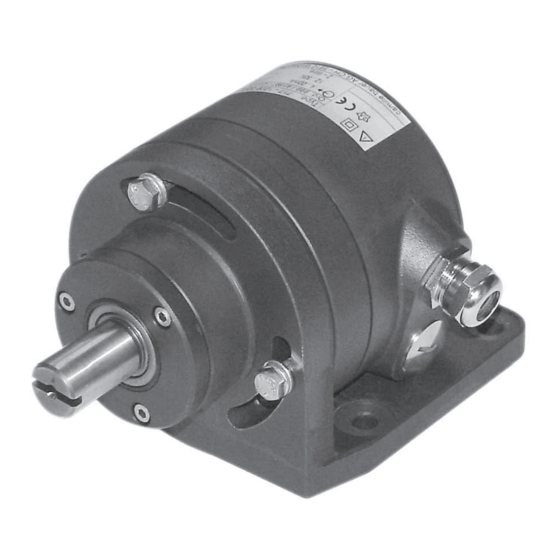
Messumformer für Drehwinkel
KINAX WT 717
Mode d'emploi
Convertisseur de mesure pour angle de rotation
KINAX WT 717
Operating Instructions
Transmitter for angular rotation
KINAX WT 717
WT 717 B d-f-e
151 259-05
12.11
Advertisement
Chapters
Table of Contents

Related Manuals for Camille Bauer KINAX WT 717


Summary of Contents for Camille Bauer KINAX WT 717
- Page 1 Betriebsanleitung Messumformer für Drehwinkel KINAX WT 717 Mode d’emploi Convertisseur de mesure pour angle de rotation KINAX WT 717 Operating Instructions Transmitter for angular rotation KINAX WT 717 WT 717 B d-f-e 151 259-05 12.11 Camille Bauer AG Aargauerstrasse 7...
- Page 2 Geräte dürfen nur fachgerecht entsorgt werden! Les appareils ne peuvent être éliminés que de façon appropriée! The instruments must only be disposed of in the correct way!
-
Page 3: Table Of Contents
5. Technische Daten ............4 6. Montage ..............5 2. Kurzbeschreibung 7. Winkelstellung defi nieren ..........5 Der Messumformer KINAX WT 717 erfasst kontaktlos die 8. Elektrische Anschlüsse ..........6 Winkelstellung einer Welle und formt sie in einen einge- 8.1 Leitungen anschliessen ......... 6 prägten, dem Messwert proportionalen Gleichstrom um. -
Page 4: Aufschlüsselung Der Varianten
4. Aufschlüsselung der Varianten Messausgang Hilfsenergie: H = 12 bis 33 V DC Erklärung der Bestell-Ziffern 1. bis 9. (möglich bei der Standard-Ausfüh- Bestell-Code 717– rung, Nicht Ex) H = 12 bis 30 V DC Ausführung des Messumformers (erforderlich bei der Ex-Ausführung, Standard, Zündschutzart Eigensicherheit Messausgang nicht eigensicher... -
Page 5: Montage
120º mi-Verschlusses (5.1) wird der Programmieranschluss (5) zugänglich (siehe Abschnitt "8.1 Leitungen anschliessen"). ±0,2 KINAX WT 717 nach Bild 4 mit der Programmiereinrichtung verbinden. Konfi gurations-Software 2W2 starten. Gerät – wenn nötig – mit den gewünschten Messbereichsdaten konfi gurieren. Der Drehwinkelmessumformer darf nur ausser- halb des Ex-Bereiches programmiert werden! Die max. -
Page 6: Elektrische Anschlüsse
Drahtquerschnitte. PK 610 auf OFF). 2. Messobjekt in Nullstellung bringen, d.h. in die Position, in (5.1) der der KINAX WT 717 den Ausgangsstrom 4 mA ausgeben (3.2) soll. Mit dem virtuellen Drehknopf «Nullpunkt» solange verstellen, bis das Ausgangssignal stimmt. 3. Messobjekt in Endstellung bringen, d.h. in die Position, in der der KINAX WT 717 den Ausgangsstrom 20 mA ausge- (4.1) -
Page 7: Simulationsmodus
10. Simulationsmodus 12. Zubehör Die Konfi gurations-Software 2W2 bietet die Möglichkeit, Bestell- Bezeichnung den KINAX WT 717 im Simulationsmodus zu betreiben. Die Simulation des Messwertes ermöglicht das Austesten Programmierkabel PK 610 137 887 der nachgeschalteten Wirkungskette bereits während der Installation. -
Page 8: Consignes De Sécurité
6. Montage ..............10 2. Description brève 7. Défi nir la position angulaire ........10 Le convertisseur de mesure KINAX WT 717 est destiné à la 8. Raccordements électriques ........11 conversion, sans contact, de la position angulaire d’un axe 8.1 Raccorder les lignes .......... -
Page 9: Codages Des Variantes
4. Codage des variantes Sortie de mesure Alimentation auxiliaire: H = 12 à 33 V CC Explication des chiffres de commande 1. à 9. (possible avec l’exécution standard, non-Ex) Code de cde 717– H = 12 à 30 V CC Exécution du convertisseur de mesure (nécessaire pour l’exécution Ex, mode Standard,... -
Page 10: Montage
Les convertisseurs de mesure pour angle de rotation (Suite): Exécution Ex KINAX WT 717 n’ont pas besoin d’un marquage du point voir certifi cat d’essai du modèle type mécanique de zéro (peut toutefois être prévu sur demande ci-joint du client, voir Fig. 3a). -
Page 11: Raccordements Électriques
fi ls de max. 1,5 mm 2. Amener l’installation de mesure dans la position zéro, c.à.d. dans la position dans laquelle le KINAX WT 717 doit (5.1) sortir un courant de 4 mA. Tourner le bouton virtuel «Zéro»... -
Page 12: Mode De Simulation
Le logiciel de confi guration 2W2 offre la possibilité de faire No de Désignation travailler le KINAX WT 717 en mode de simulation. Il est ainsi cde. possible de vérifi er le fonctionnement de la chaine de mesure Câble de programmation PK 610 137 887 complète pendant l’installation. -
Page 13: Safety Instructions
2. Brief description 6. Mounting ..............15 7. Adjusting the angle ........... 15 The KINAX WT 717 converts the angular position of a shaft into a load-independent direct current signal, proportional 8. Electrical connections ..........16 to the angular position. The measuring range, sense of ro- 8.1 Connecting transmitter ........ -
Page 14: Specifi Cation And Ordering Information
4. Specifi cation and ordering information Measuring output Power supply: H = 12 to 33 V DC Signifi cance of the digits 1. to 9. (possible with standard version, Order Code 717– non-Ex) H = 12 to 30 V DC Version of the transmitter (necessary with Ex version, type of Standard,... -
Page 15: Mounting
Climatic rating 7. Adjusting the angle (continuation): Ex version Angular position transmitters of the KINAX WT 717 range do see enclosed type examination not require a mechanical zero position mark (however, this certifi cate is made if required by the customer, see Fig. 3a). -
Page 16: Electrical Connections
PK 610 on the OFF position). (5.1) 2. Place the measuring device in the zero position, i.e. in the (3.2) position in which the KINAX WT 717 should output 4 mA. Adjust with the “ZERO” virtual knob until the output is correct. (4.1) 3. -
Page 17: Simulation Mode
12. Accessories The 2W2 confi guration software supports the operation of Order Description the KINAX WT 717 in simulation mode. The simulation of the measured value allows the subsequent chain of devices to Programming cable PK 610 137 887 be tested during the installation phase. -
Page 18: Mass-Skizzen
14. Mass-Skizzen / Croquis d’encombrements / Dimensional drawings M6 x 15 KINAX WT 717 32.5 ±0.2 76.5 PG 11 M6 x 15 KINAX WT 717 mit Zusatzgetriebe KINAX WT 717 avec engrenage additionnel 32.5 KINAX WT 717 ±0.2 76.5 PG 11 with additional gear approx. - Page 19 55° KINAX WT 717 mit Flansch KINAX WT 717 avec fl asque KINAX WT 717 with fl ange 32.5 PG 11 11.5 ±0.2 55° KINAX WT 717 mit Zusatzgetriebe und Flansch KINAX WT 717 avec engrenage additionnel et fl asque...
-
Page 20: Konformitätsbescheinigung
15. Konformitätsbescheinigung / Certifi cat de conformité / Declaration of conformity EG - KONFORMITÄTSERKLÄRUNG EC DECLARATION OF CONFORMITY D o k u m e n t - N r . / K i n a x W T 7 1 7 _ C E - k o n f . D O C D o c u m e n t .
Need help?
Do you have a question about the KINAX WT 717 and is the answer not in the manual?
Questions and answers