Table of Contents
Advertisement
Quick Links
ADD-A-VALVE
Jomar requires that the Add-A-Valve® installer view the Jomar installation video prior to attempting
installation. Failure to do so will relinquish Jomar from any and all liability for improperly installing
an Add-A-Valve® device. In this case, Jomar will not be responsible, nor will it exchange or provide a
refund for any improperly installed Add-A-Valve®.
Video is available for viewing on the Jomar website at: www.jomarvalve.com/aav.html
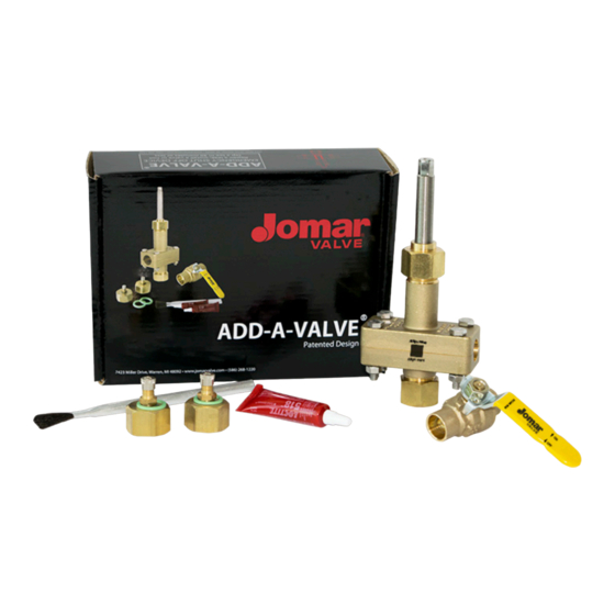
Included Parts
Before you start:
• Verify that there is not a risk of deadheading a pump during installation.
• Isolate the Add-A-Valve location or reduce the flow rate as much as the system will allow.
Ideally, install the Add-A-Valve on a static line.
NOTE: The Jomar Add-A-Valve® is engineered for ONE-TIME use as an emergency shut-off
INSTALLATION INSTRUCTIONS
• Add-A-Valve®
• Jomar S-100NE
• Gasket Sealant (Loctite® 518)
• Brush
• Extra Viton® O-Rings (2)
• Shraeder® test caps (2)
device! Once the stem cutter has been raised, DO NOT lower it again.
ATTENTION:
• Needle-nose pliers
• Flat head screwdriver
• Hammer
• Adjustable wrench
• Ratchet wrench
• Open-end wrench
• Emery cloth
• Optional for Double Stem Models (1-1/4" - 2"):
º
º Cordless backup battery recommended
®
For Technical Support
Call 1-800-325-5690 or visit:
jomarvalve.com/aav.html
Additional Tools
Drill (electric or cordless) with socket adapter
1
Advertisement
Table of Contents

Related Manuals for JOMAR Add-A-Valve


Summary of Contents for JOMAR Add-A-Valve
- Page 1 Failure to do so will relinquish Jomar from any and all liability for improperly installing an Add-A-Valve® device. In this case, Jomar will not be responsible, nor will it exchange or provide a refund for any improperly installed Add-A-Valve®.
- Page 2 CAUTION Pipe hanger supports should be installed on both sides of the Add-A-Valve® to 12” eliminate stress at the ends of the valve. If hangers cannot be installed, it is NOT recommended to use the Add-A-Valve®. Step 1 Before installing the Add-A-Valve®, clean the copper tubing with a fine emery cloth until the copper tubing has a bright, shiny finish. Step 2 Disassemble the Add-A-Valve® body by removing the four (4) 316 stainless steel bolts. Step 3 Apply a liberal amount of the provided gasket sealant (Loctite 518) ® and brush evenly across the entire body half surface. Apply the gasket sealant to both body halves and allow 1-2 minutes for dry time.
- Page 3 CAUTION Pipe hanger supports should be installed on both sides of the Add-A-Valve® 12” to eliminate stress at the ends of the valve. If hangers cannot be installed, it is NOT recommended to use the Add-A-Valve®. Step 4 CORRECT INCORRECT Assemble the two body halves around the copper tubing. NOTE: Be sure the stem cutter is backed out all the way so that the cutter does not make contact with the copper tubing. Ensure even gap Uneven gap distribution distribution on all axes/ can lead to install failure. directions.
- Page 4 NOTE: Ensure the stem cutter is backed out all the way, to prevent the cutter from making contact with the copper tubing. Now, engage the stem cutter. Determine what size Add-A-Valve® you have and follow the corresponding directions: Step 10 SINGLE STEM For sizes 1/2” to 1”...
Need help?
Do you have a question about the Add-A-Valve and is the answer not in the manual?
Questions and answers