Table of Contents
Advertisement
Quick Links
Advertisement
Table of Contents

Related Manuals for M Solutions MS-TestPro MS103TDs


Summary of Contents for M Solutions MS-TestPro MS103TDs
- Page 1 MS-TestPro Test Device Model MS103TDs / MS104B User’s Manual Revision A15...
- Page 2 MS-TestPro User’s Manual MSolutions, Ltd. Sales: sales@m4sol.com Support: support@m4sol.com Web: www.m4sol.com The information contained in this document, or any addendum or revision thereof is proprietary of Media Solutions Ltd. And is subject to all relevant copyright, patent and other laws and treaties protecting intellectual property, as well as any specific agreement protecting Media Solutions Ltd.
- Page 3 MS-TestPro User’s Manual Revision History Revision Date Description November 2016 First issue February 2017 General update • Explanation of HDBaseT Link classes • How to connect the test device for EDID March 2017 • Description of test cases • USB connectivity indicator April 2017 Cable certification –...
-
Page 4: Table Of Contents
MS-TestPro User’s Manual Table of Contents INTRODUCTION ............................6 MS-T .......................... 8 ODELS ..........................8 TANDARD ODULES ........................ 9 PTIONAL ODULES PRODUCT DESCRIPTION ........................10 ............................10 VERVIEW ............................11 ODELS ............................. 12 UBSYSTEMS ..........................13 UPPORT INSTALLATION ............................14 ......................... - Page 5 MS-TestPro User’s Manual ........................58 YSTEM NITIALIZATION ........................59 ERFORMING THE ESTS 5.3.1 Main Screen ..........................59 5.3.2 Information Menu ........................59 5.3.3 HDBaseT Analyzer........................61 5.3.3.1 Basic Analysis........................... 62 5.3.3.2 Performance Management ......................64 5.3.3.3 Configuration........................... 66 5.3.4 Tools ............................69 5.3.4.1 HDMI Generator ..........................
-
Page 6: Introduction
MS-TestPro User’s Manual Introduction This document is intended as a guide for installation and operation of the MS-TestPro HDBaseT Test Device from Media Solutions Ltd. The MS-TestPro test device provides an elegant solution for in-the-field testing of HDBaseT-based communications systems and cabling. Use the MS-TestPro device to test and certify the HDBaseT performance and link quality of CATx cabling before performing installations. - Page 7 MS-TestPro User’s Manual Why do you need the MS-TestPro HDBaseT test device? You’ve finished wiring the audiovisual system, and have connected the audio/visual devices over the HDBaseT link. You can see the picture and hear the sound. Everything is OK, right? No! A link test is essential in guaranteeing perfect performance.
-
Page 8: Ms-Testpro Models
MS-TestPro User’s Manual MS-TestPro Models Users can choose between two MS-TestPro models: ◼ Wi-Fi Client Model, with 3.5” screen, built-in HDMI pattern generator, and Wi-Fi interface for browser-based management (MS103TDs) Figure 3: MS103TDs ◼ Battery based Wi-Fi Client Model, with 3.5” screen, built-in HDMI pattern generator and Wi-Fi interface for browser-based management (MS104B) Figure 4: MS104B Standard Modules... -
Page 9: Optional Add-On Modules
MS-TestPro User’s Manual Optional Add-On Modules ◼ The HDBaseT Spec 2.0 Modules (Tx and Rx units) are available as an optional add-on that can be used with any of the above-mentioned tester models. Figure 6: HDBaseT Spec 2.0 Tx/Rx Modules ◼... -
Page 10: Product Description
MS-TestPro User’s Manual Product Description Overview The basic MS-TestPro HDBaseT test device is composed of 3 units: ◼ Main unit – the MS-TestPro chassis – containing a power supply, USB connector, and 3.5-inch touch screen. ◼ HDBaseT transmitter module – for transmitting HDBaseT traffic to sink devices, such as projectors or television sets ◼... -
Page 11: Models
MS-TestPro User’s Manual Models The MS-TestPro HDBaseT Test Device is supplied in a variety of models and add-on modules: Table 1: MS-TestPro Models Model Description HDBaseT tester main unit with 3.5" touch display, built-in HDMI pattern MS103TDs generator, and Wi-Fi connection for smart devices MS104B Battery based HDBaseT tester main unit with 3.5"... -
Page 12: Subsystems
MS-TestPro User’s Manual Subsystems Table 3 below describes the MS-TestPro test device’s subsystems. Table 3: MS-TestPro Subsystems Subsystem Description • Main unit Power supply, 48V, 0.5A, positive polarity central pin • MS103TDs USB 2.0 port – for memory stick connectivity •... -
Page 13: Hdbaset Support
MS-TestPro User’s Manual HDBaseT Support The MS-TestPro test device integrates a Valens VS100 HDBaseT Class A or VS2310 HDBaseT class C chipset, including transmit and receive ICs. The class A chipset supports HDBaseT Specification 1.0, and is compatible with HDBaseT Specification 2.0, allowing it to work with HDBaseT devices of the following classes: Table 4: MS-TestPro Compatibility with HDBaseT Classes Class... -
Page 14: Installation
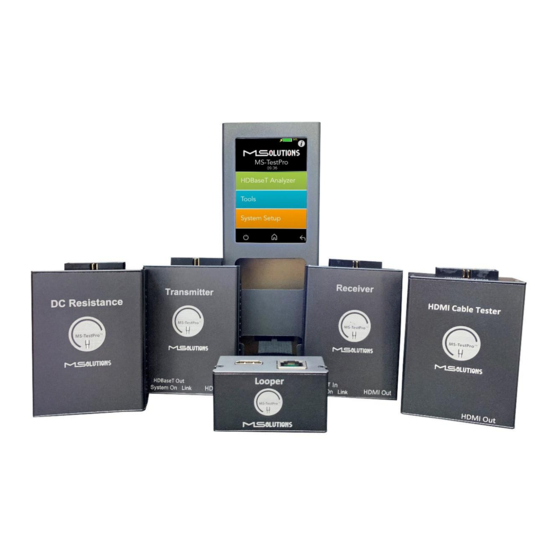
MS-TestPro User’s Manual Installation Unpacking the Unit The complete MS-TestPro HDBaseT Test Device kit is depicted in Figure 9 below. Figure 9: MS-TestPro HDBaseT Test Device Kit Page 14 of 113... - Page 15 MS-TestPro User’s Manual Figure 10: MS-TestPro HDBaseT Test Device Kit Contents The TestPro system is supplied with the following components: Table 5: MS-TestPro Components Number Component Main unit Transmitter module Receiver module External 48 VDC power supply for MS103TDs or 12.6 VDC charger for MS104B Pluggable PoH Adapter –...
-
Page 16: Operating The Touchscreen
MS-TestPro User’s Manual Operating the Touchscreen Test Setup This section describes the physical setup and connectivity schemes used to perform tests using MS- TestPro. ◼ Testing MS-TestPro Modules ◼ Connection to System Under Test (SUT) IMPORTANT * Make sure that you complete all cable connections before powering up the MS-TestPro test device. * Always power down the unit for cartridge replacement. - Page 17 MS-TestPro User’s Manual Internal Pattern Generator HDMI HDMI HDBaseT Figure 12: MS-TestPro Modules Test Setup using Internal Pattern Generator ➔ To setup the system for testing: Insert the Transmitter or Receiver module into the MS-TestPro main unit in the lower slot – this module will be defined as the local module.
-
Page 18: Connection To System Under Test (Sut)
MS-TestPro User’s Manual Insert the 48 VDC power supply connector into the designated socket in the main unit to power the device. NOTE The device will not power up unless a local module has been inserted into the lower slot of the device. -
Page 19: Performing The Tests
MS-TestPro User’s Manual ◼ Connecting the CATx cable to the MS-TestPro receiver module, and connecting the receiver module to the sink device with an HDMI cable. Insert the power supply connector into the designated socket in the main unit to provide power. -
Page 20: Information Menu
MS-TestPro User’s Manual ◼ Log Analyzer: For continuous testing up to 24 hours. HDBaseT Firmware Update: To update the firmware of 3rd party HDBaseT units. ◼ ◼ DC Resistance testing (supported if the DCR module is inserted) ◼ HDMI cable testing (supported if the HCT module is inserted) ◼... -
Page 21: Hdbaset Analyzer
MS-TestPro User’s Manual 4.2.3 HDBaseT Analyzer To get to HDBaseT Analyzer menu, tap on the HDBaseT analyzer button as shown in the figure below: Figure 17: Selecting the HDBaseT Analyzer Menu The following screen will appear: Figure 18: HDBaseT Analyzer Screen Page 21 of 113... -
Page 22: Basic Analysis
MS-TestPro User’s Manual 4.2.3.1 Basic Analysis The Basic Analysis function is used to report on HDBaseT link quality. To analyze the link, tap on the Basic Analysis button, as shown in the figure below. Figure 19: Selecting Basic Analysis The Basic Analysis page appears as shown in the figure below. Figure 20: Basic Analysis Page Page 22 of 113... -
Page 23: Performance Management
MS-TestPro User’s Manual The basic analysis page displays the following information: ◼ General Link Quality. Red, yellow, green as defined below. ◼ Transmitter Link Quality. Red, yellow, green as defined below. ◼ Receiver Link Quality. Red, yellow, green as defined below. ◼... - Page 24 MS-TestPro User’s Manual NOTE When monitoring performance, the transmitter controls are always displayed on the left side, the receiver controls are always displayed on the right, as shown below in Figure 22. Figure 22: Performance Monitoring Screen. MaxErr Screen – Displaying Graph & Data. The screen appears, displaying receiver (Rx) data.
-
Page 25: Configuration
MS-TestPro User’s Manual The data appear in the graph that is displayed on the top of the screen, as shown in Figure 22 above. The graphical display is continuously updated. Figure 23: MseErr Screen – Displaying Graph & Data 4.2.3.3 Configuration To view the current system configuration, tap on the Configuration button, as shown in the figure below. - Page 26 MS-TestPro User’s Manual The configuration screen appears as shown in the figure below: HDCP Indicator Figure 25: Rx and Tx Configuration Screens The remote and local HDBaseT transceivers are identified – as either transmitter or receiver – and displayed at the bottom of the page. Tap to select Receiver or Transmitter. The current selection appears on a gray background.
-
Page 27: Tools
MS-TestPro User’s Manual Cable Length. Approximate cable length calculation (accuracy level 10%), in Meters or Feet. ◼ ◼ Video Status. Indicates whether HDCP content is being transmitted. ◼ Video On. HDMI transmission without HDCP content. ◼ HDCP On. HDMI transmission with HDCP content. ◼... -
Page 28: Hdmi Generator
MS-TestPro User’s Manual Figure 27: Tools Page 4.2.4.1 HDMI Generator The HDMI pattern generator provides ability to generate a variety of HDMI display patterns in a wide range of resolutions. The HDMI pattern generator screen appears as shown below in Figure 28. Figure 28: HDMI Generator Screen Page 28 of 113... - Page 29 MS-TestPro User’s Manual To generate an HDMI pattern, select a Resolution, a Refresh rate and a Pattern from the lists. The selections appear in a gray background. Tap Apply to initiate the generation for a default duration of 20 seconds Tap on Advanced to select from additional resolutions and patterns.
-
Page 30: Edid Analyzer
MS-TestPro User’s Manual 4.2.4.2 EDID Analyzer You can use EDID to access information on the display capabilities of HDMI sink devices. There are two test setups that you can use to access the information: ◼ Connecting the MS-TestPro test device to an HDMI sink device via an HDBaseT link. ◼... -
Page 31: Certification Report
MS-TestPro User’s Manual To save EDID data to the tester internal memory, tap the Save button. To download EDID data, connect the USB memory stick and tap the Download button. Two files will be saved – EDIDXXXX.txt and EDIDXXXX.bin. To delete EDID data from tester, select the files to delete and tap the Delete button. 4.2.4.3 Certification Report The certification report menu provides the following capabilities:... - Page 32 MS-TestPro User’s Manual IMPORTANT The HDMI cable must be connected to the Internal Generator to ensure that HDMI traffic is running on the HDBaseT link. Select Certification report >> Run (Generate Data), as shown below in Figure 34: Figure 34: Generate Report Data A progress bar appears in the window: Figure 35: Generating Report Data Page 32 of 113...
- Page 33 MS-TestPro User’s Manual After the data is generated, the line certification results appear at the top of the screen, as shown in the figure below. To save the generated data files, insert the USB memory stick and tap on the Report Files button (see the figure below). Figure 36: Downloading Report Data In the following screen appears a list of certification tests that were run in the unit: Figure 37: Certification Report Data File Options...
- Page 34 MS-TestPro User’s Manual Insert a USB memory stick into one of the USB ports of the MS-TestPro device. Select a report data file or files from the list as shown in Figure 37, and tap Download to save the file to the memory stick. Wait until the following message disappears: Figure 38: Message - Downloading Report Data To delete files, select one or more report data files from the list, and tap Delete.
- Page 35 MS-TestPro User’s Manual To generate a printable certification report based on the downloaded data, see Appendix D: Generating an HDBaseT Certification Report. 4.2.4.3.2 Profile Configuration To choose the appropriate profile, tap the Cable Profile button based on the cable which is used. If the desired cable is not on the list, tap on Standard Profile, note the selected profile appears on a gray background.
- Page 36 MS-TestPro User’s Manual 4.2.4.3.3 Setting up a Custom Logo We have now enabled the MS-TestPro to imprint your own custom logo on the top left corner of each certification report you run. The process to upload your custom logo is:- 1.
-
Page 37: Log Analyzer
MS-TestPro User’s Manual 4.2.4.4 Log Analyzer The comprehensive Log Analyzer function measures over sixty different parameters. It is intended to track random failures over a long period of time. The recommended test duration is 24 hours, allowing you capture the performance of the cable during the course of an entire day. This enables you to perform an in-depth analysis of any problem. - Page 38 MS-TestPro User’s Manual ➔ To export log files to a USB memory stick: Insert a USB memory stick into one of the USB ports. Upon connection, the USB indicator is displayed at the bottom of the screen. To distribute a log for analysis, mark files and tap Download button. The transmitter and receiver logs that you generated are copied to the USB memory stick.
- Page 39 MS-TestPro User’s Manual Figure 45: Log Report Page 39 of 113...
-
Page 40: Hdbaset Firmware Update
MS-TestPro User’s Manual 4.2.4.5 HDBaseT Firmware Update ➔ To upgrade 3rd party Tx or Rx remote unit firmware: Prepare a USB memory stick with the upgrade file xxx.Hex in the root folder of the stick. Connect the stick to one of the USB ports in the MS-TestPro device. Tap on the HDBaseT FW Update button on the Tools screen. - Page 41 MS-TestPro User’s Manual GUI buttons: Automatic selection of remote device Maintain the manufacturer’s configuration settings Verify programming Reset the programmed unit after programming completed Select the programming file Start programming the device Figure 47: Firmware Upgrade GUI Wait for the progress bar to disappear: Figure 48: Firmware Update in Progress To verify if the upgraded unit was successfully upgraded, access the Configuration menu and read the current HDBaseT firmware version.
-
Page 42: Dcr - Dc Resistance Testing
MS-TestPro User’s Manual 4.2.4.6 DCR - DC Resistance Testing Using the MS-TestPro DCR and Looper modules, you can test the DC resistance of CATx cables, and check their ability to provide a sufficient level of PoH (Power over HDBaseT) powering. The DC Resistance module is inserted into the lower slot in the MS-TestPro main unit, while the CATx cable is connected to the DC Resistance module at one end, and to the Looper module at the other end, as depicted in the figure below:... - Page 43 MS-TestPro User’s Manual Figure 50: Loop Resistance Results Tap on the Parallel DC Resistance Unbalanced button to display the parallel resistance of the CATx two conductors in each cable pair. For each pair, the difference is expressed in ohms, as shown in the figure below. Figure 51: Parallel DC Resistance Unbalanced Results Page 43 of 113...
- Page 44 MS-TestPro User’s Manual Tap on the Pair-to-Pair Resistance Unbalanced button to display the difference in DC resistance between the four pairs in the cable. For each pair, the difference is expressed in ohms, as shown in the figure below. A difference of under 0.2 ohms or 5% (the higher between the two) indicates that the pair should be capable of delivering the required common-mode current needed to effectively support PoH and data transmission over the pair.
- Page 45 MS-TestPro User’s Manual To save DCR data to the tester internal memory, tap the Save button. To download DCR data to a USB memory stick, tap the Download button. A screen containing a list of DCR data files appears as shown in the figure below. Figure 53: List of DC Resistance Reports in PDF Format Select one or more PDF files, and perform one of the following actions: ◼...
-
Page 46: Hct - Hdmi Cable Testing
MS-TestPro User’s Manual 4.2.4.7 HCT - HDMI Cable Testing Using the MS-TestPro HDMI Cable Tester and Looper modules, you can test the quality of HDMI cables before their installation. In order to reduce costs and boost profits, some HDMI cable suppliers sell cables with missing or shorted wires. - Page 47 MS-TestPro User’s Manual ➔ To test the quality of an HDMI cable: Attach the cable to the HDMI Cable Tester and Looper modules as shown in Figure 55 above. From the Tools page, tap on the HDMI Cable Tester button. Figure 56: HDMI Cable Tester Button The HDMI Cable Tester page appears as shown in the figure below.
- Page 48 MS-TestPro User’s Manual NOTE In this description, the Compatibility and Sweep tests are presented separately. You can check both the Compatibility and Sweep boxes to run the two tests simultaneously. The MS-TestPro begins testing the cable’s compatibility with the HDMI bandwidth. When the test is complete, a summary screen appears.
- Page 49 MS-TestPro User’s Manual Tap Save to save the test results in a report format. Following generation of the report, tap Download to copy the report to a disk-on-key attached to the tester’s USB port. File is created into PDF automatically. To perform the Sweep test, return to the HDMI Cable Tester page appears as shown in the figure below.
- Page 50 MS-TestPro User’s Manual Figure 61: Sweep Test in Progress At the end of the test, the Start button appears. Click on the button if you wish to run another Sweep test. Figure 62: Sweep Test Complete Page 50 of 113...
-
Page 51: System Setup
MS-TestPro User’s Manual System Setup To perform setup functions, tap on the System Setup main screen button, as shown in the figure below. Figure 63: Selecting System Setup The System Setup screen (see Figure 64 below) offers the following information and functionalities: ◼... -
Page 52: System Upgrade
MS-TestPro User’s Manual 4.3.1 System Upgrade ➔ To upgrade the MS-TestPro System Software: Prepare a USB memory stick with the upgrade file updateXXX.mst in the root folder. Connect the stick to one of the USB ports in the MS-TestPro device. Select the updateXXX.mst file and tap on the System Upgrade button (see the picture below). -
Page 53: System Settings
MS-TestPro User’s Manual Figure 66: System Reboot Screens The system will reboot in about 15-20 seconds. 4.3.3 System Settings The System Settings screen provides access to the system configuration. The System Settings screen is depicted in the figure below. The upper part of the screen displays read-only system information. Figure 67: System Settings screen Page 53 of 113... -
Page 54: Date/Clock Settings
MS-TestPro User’s Manual The System Settings page provides the following information and configuration options for the MS-TestPro system: ◼ App Version. Tester firmware version. ◼ Local IP. Allocated IP address (for future use). ◼ Features. A list of supported features: ◼... -
Page 55: Shutdown
MS-TestPro User’s Manual Set Date/Clock values and press the Apply button. Note: Date and time will be set automatically when connecting Tester to a PC using a Wi-Fi connection. Shutdown This section describes how to safely shut down the MS-TestPro test device. ➔... -
Page 56: Operating The Wi-Fi Client
MS-TestPro User’s Manual Operating the Wi-Fi Client You can manage the MS-TestPro test unit using a Wi-Fi enabled computing device (mobile phone, tablet, PC) equipped with a browser. The device connects as a client to the web server software embedded in the test unit. Connecting the Wi-Fi Device The following steps describe how to connect your Wi-Fi client device to the MS-TestPro test unit. - Page 57 MS-TestPro User’s Manual Select the "Media-Solutions" network from the list, and tap on the Connect button that appears on the screen (see Figure 71 below). Figure 71: Connecting to the Media-Solutions Network Initialize the system as described in the following section. Page 57 of 113...
-
Page 58: System Initialization
MS-TestPro User’s Manual System Initialization The following steps describe how to initialize the MS-TestPro client on your Wi-Fi device and connect it to the test unit. ➔ To initialize the MS-TestPro system on your Wi-Fi client: Open your browser and enter the URL of the MS-TestPro System: 192.168.11.1 as shown in the figure below. -
Page 59: Performing The Tests
MS-TestPro User’s Manual Performing the Tests 5.3.1 Main Screen The main screen (see the figure above) offers the following functionalities: ◼ Information. The icon provides access to informative guidelines and system documentation. ◼ HDBaseT Analyzer ◼ Basic Analysis: Basic Pass/Fail report. ◼... - Page 60 MS-TestPro User’s Manual Figure 74: Information Menu Page 60 of 113...
-
Page 61: Hdbaset Analyzer
MS-TestPro User’s Manual 5.3.3 HDBaseT Analyzer To get to HDBaseT Analyzer menu, tap on the HDBaseT Analyzer button as shown in the figure below: Figure 75: Selecting the HDBaseT Analyzer Menu The following screen will appear: Figure 76: HDBaseT Analyzer Screen Page 61 of 113... -
Page 62: Basic Analysis
MS-TestPro User’s Manual 5.3.3.1 Basic Analysis The Basic Analysis function is used to report on HDBaseT link quality. To analyze the link, tap on the Basic Analysis button, as shown in the figure below. Figure 77: Selecting Basic Analysis Page 62 of 113... - Page 63 MS-TestPro User’s Manual The Basic Analysis page appears as shown in the figure below. Figure 78: Basic Analysis Page The basic analysis page displays the following information: ◼ General Link Quality. Red, yellow, green as defined below. ◼ Transmitter Link Quality. Red, yellow, green as defined below. ◼...
-
Page 64: Performance Management
MS-TestPro User’s Manual 5.3.3.2 Performance Management To access performance management functionality, tap on the Performance button, as shown in the figure below. Figure 79: Selecting Performance Monitoring The system provides performance monitoring of the four HDBaseT channels (each associated with a twisted pair) in the CATx cable –... - Page 65 MS-TestPro User’s Manual NOTE When monitoring performance, the transmitter controls are always displayed on the left side, the receiver controls are always displayed on the right, as shown below in Figure 22. Figure 80: Performance Monitoring Screen. MaxErr Screen – Displaying Graph & Data. The screen appears, displaying receiver (Rx) data.
-
Page 66: Configuration
MS-TestPro User’s Manual To display data, tap on the MaxErr or the MseErr button on the Transmitter or Receiver side. The background of the tapped button appears in gray. The data appear in the graph that is displayed on the top of the screen, as shown in the figure below. The graphical display is continuously updated. - Page 67 MS-TestPro User’s Manual Figure 82: Selecting Configuration Management The Rx configuration screen appears as shown in the figure below: HDCP Indicator Figure 83: Rx Configuration Screen Page 67 of 113...
- Page 68 MS-TestPro User’s Manual The Tx configuration screen appears as shown in the figure below: HDCP Indicator Figure 84: Tx Configuration Screen The remote and local HDBaseT transceivers are identified – as either transmitter or receiver – and displayed at the top of the page. NOTE The system correctly identifies the local and remote transceivers –...
-
Page 69: Tools
MS-TestPro User’s Manual Cable Length. Approximate cable length calculation (accuracy level 10%), in Meters or Feet. ◼ ◼ Video Status. Indicates whether HDCP content is being transmitted. ◼ Video On. HDMI transmission without HDCP content. ◼ HDCP On. HDMI transmission with HDCP content. ◼... -
Page 70: Hdmi Generator
MS-TestPro User’s Manual The Tools page is depicted in the figure below. Figure 86: Tools Page 5.3.4.1 HDMI Generator The HDMI pattern generator provides the ability to generate a variety of HDMI display patterns in a wide range of resolutions. The HDMI pattern generator screen appears as shown below. - Page 71 MS-TestPro User’s Manual To begin generating HDMI pattern, select the Resolution and Pattern from the list boxes and tap Apply. Table 7: Supported HDMI Resolutions Resolution Frequency Resolution Frequency 1080p 24Hz 720p 60Hz 1080p 25Hz 1080i 60Hz 30Hz 480i 60Hz 1080p 30Hz 1080i...
- Page 72 MS-TestPro User’s Manual Blue Checkers Figure 88: Supported HDMI Patterns The pattern will be activated for an indefinite period, as shown in the figure below. To deactivate the pattern, reset the MS-TestPro device. Figure 89: Reset the MS-TestPro to Deactivate the Pattern Page 72 of 113...
-
Page 73: Edid Analyzer
MS-TestPro User’s Manual 5.3.4.2 EDID Analyzer You can use EDID to access information on the display capabilities of HDMI sink devices. There are two test setups that you can use to access the information: ◼ Connecting the MS-TestPro test device to an HDMI sink device via an HDBaseT link. ◼... -
Page 74: Certification Report
MS-TestPro User’s Manual ➔ To access display capabilities using EDID: Connect the MS-TestPro test device to the HDMI sink device using one of the methods described above. Tap on the EDID Analyzer button to access information on the display capabilities of the HDMI sink device. - Page 75 MS-TestPro User’s Manual 5.3.4.3.1 Run (Generate Data) The HDBaseT report data collection feature is used to collect the data required to perform HDBaseT cable analysis. ➔ To access data for HDBaseT cable analysis: Connect the MS-TestPro test device to both ends of the CATx cable, as shown below in Figure 33: ◼...
- Page 76 MS-TestPro User’s Manual Select Certification report >> Run (Generate Data), as shown below: Figure 93: Generate Report Data A progress bar appears in the window: Figure 94: Generating Report Data Page 76 of 113...
- Page 77 MS-TestPro User’s Manual After the data is generated, the line certification results appear at the top of the screen, as shown in the figure below. To save the generated data files, insert the USB memory stick and tap on the Download (Report Data) button (see the figure below). Figure 95: Downloading Report Data Page 77 of 113...
- Page 78 MS-TestPro User’s Manual In the following screen appears a list of certification tests data files: Figure 96: Certification Report Data File Options To download file to USB flash memory, select the USB radio button, insert a USB memory stick into one of the USB ports of the MS-TestPro device. Select a report data file or files from the list as shown in Figure 37, and tap Download to save the file to the memory stick.
- Page 79 MS-TestPro User’s Manual Figure 98: Certification Report To see generated PDF Report check PDF on the Figure 96 and Download to PC or USB. Figure 99: PDF Certification Report Download Page 79 of 113...
- Page 80 MS-TestPro User’s Manual To delete files, select a report data file or files from the list, and tap Delete. To generate a printable certification report based on the downloaded data, see Appendix D: Generating an HDBaseT Certification Report. 5.3.4.3.2 Profile Configuration To choose the appropriate profile, tap the Profile button based on the cable which is used.
-
Page 81: Log Analyzer
MS-TestPro User’s Manual Figure 101: Download PDF Creator Software 5.3.4.4 Log Analyzer The comprehensive Log Analyzer function measures over sixty different parameters. It is intended to track random failures over a long period of time. The recommended test duration is 24 hours, allowing you capture the performance of the cable during the course of an entire day. - Page 82 MS-TestPro User’s Manual 5.3.4.4.1 Log Generation ➔ To perform log generation: To begin log generation, tap on the Log Analyzer, then the Start button. To end log generation, tap on Stop button as shown in the figure below. The system generates transmitter and receiver logs.
-
Page 83: Hdbaset Firmware Update
MS-TestPro User’s Manual Figure 103: Downloading Files You can choose to copy any of the file pairs to the PC or USB memory stick. To delete files, select a file or files from the list, and tap Delete. 5.3.4.5 HDBaseT Firmware Update ➔... - Page 84 MS-TestPro User’s Manual Figure 104: Remote Unit HDBaseT Firmware Update NOTE * Do not switch off the device’s power during the upgrade! * Firmware updates are available only to 3 party remote Transmitter or Receiver units. * The HDBaseT firmware of the MS-TestPro Transmitter and Receiver cannot be upgraded GUI buttons: Automatic selection of remote device...
-
Page 85: Dc Resistance Unbalance Testing
MS-TestPro User’s Manual Wait for the progress bar to disappear. To verify if the upgraded unit was successfully upgraded, access the Configuration menu and read the current HDBaseT firmware version. See Figure 83. 5.3.4.6 DC Resistance Unbalance Testing Using the MS-TestPro DC Resistance and Looper modules, you can test the DC resistance of CATx cables, and check their ability to provide a sufficient level of PoH (Power over HDBaseT) powering. - Page 86 MS-TestPro User’s Manual Tap on the Loop Resistance button to display Loop Resistance data, as shown in the figure below. Loop resistance represents the DC loop resistance (in ohms) of a cable, and is calculated as the sum of the DC resistance of the two conductors in a pair. Resistance of under 20 ohms indicates that the pair should be capable of delivering the minimum of 80% of the power to the remote side.
- Page 87 MS-TestPro User’s Manual Tap on the Pair-to-Pair Resistance Unbalanced button to display the difference in DC resistance between the four pairs in the cable. For each pair, the difference is expressed in ohms, as shown in the figure below. A difference of under 0.2 ohms or 5% (the higher between the two) indicates that the pair should be capable of delivering the required common-mode current needed to effectively support PoH and data transmission over the pair.
-
Page 88: Hdmi Cable Testing
MS-TestPro User’s Manual 5.3.4.7 HDMI Cable Testing Using the MS-TestPro HDMI Cable Tester and Looper modules, you can test the quality of HDMI cables before their installation. In order to reduce costs and boost profits, some HDMI cable suppliers sell cables with missing or shorted wires. These substandard cables are usually discovered only when trying to stream high resolutions like 4K or run CEC commands. - Page 89 MS-TestPro User’s Manual ➔ To test the quality of an HDMI cable: Attach the cable to the HDMI Cable Tester and Looper modules as shown in Figure 110 above. From the Basic Tools page, tap on the HDMI Cable Tester button. Figure 111: HDMI Cable Tester Button The HDMI Cable Tester page appears as shown in the figure below.
- Page 90 MS-TestPro User’s Manual The MS-TestPro begins testing the cable’s compatibility with the HDMI standard. When the test is complete, a summary screen appears. In the example shown below, the cable failed the 4K/60Hz test. A list of shorted wires appears as well. If needed, tap Run to perform another Compatibility test.
- Page 91 MS-TestPro User’s Manual Tap Save to save the test results in a report format. Following generation of the report, tap Download to copy the report to your PC or to a disk-on-key attached to the tester’s USB port. To perform the Sweep test, return to the HDMI Cable Tester page appears as shown in the figure below.
- Page 92 MS-TestPro User’s Manual The figure below shows the sweep test in progress. If necessary, you can tap Stop to cancel the test. Figure 116: Sweep Test in Progress At the end of the test, the Run button appears. Click on the button if you wish to run another Sweep test.
-
Page 93: System Setup
MS-TestPro User’s Manual System Setup To perform setup functions, tap on the System Setup main screen button, as shown in the figure below. Figure 118: Selecting System Setup The System Setup screen (see Figure 64 below) offers the following information and functionalities: ◼... -
Page 94: System Upgrade
MS-TestPro User’s Manual Figure 119: System Setup screen 5.4.1 System Upgrade ➔ To upgrade the MS-TestPro System Software: Prepare a USB memory stick with the upgrade file updateXXX.mst in the root folder or copy the file to the PC directory. Connect the stick to one of the USB ports in the MS-TestPro device. -
Page 95: System Reboot
MS-TestPro User’s Manual Figure 120: System Upgrade 5.4.2 System Reboot To restart the MS-TestPro test device, tap the System Reboot button and OK, as shown in the figure below. Figure 121: System Reboot Screens The system will reboot in about 10 seconds. Page 95 of 113... -
Page 96: System Settings
MS-TestPro User’s Manual 5.4.3 System Settings The System Settings screen provides access to the system configuration. The System Settings screen is depicted in the figure below. The upper part of the screen displays read-only system information. Figure 122: System Settings Screen The System Settings page provides the following information and configuration options for the MS-TestPro system: ◼... -
Page 97: Date/Clock Setting
MS-TestPro User’s Manual 5.4.3.1 Date/Clock Setting Figure 123: Date/Clock settings screen Set Date/Time values and press the Apply button. Note: Date and time will be set automatically when connecting Tester to a smart device using a Wi-Fi connection. Shutdown This section describes how to safely shut down the MS-TestPro test device. ➔... -
Page 98: Use Cases
MS-TestPro User’s Manual Use Cases This chapter contains use cases for a variety of deployment scenarios. Cable Test Using the MS-TestPro, you can test the ability of a CATx cable (CAT5e and above) to transmit HDBaseT signals over lengths of 100m and more. ◼... -
Page 99: Crimping Quality Test
MS-TestPro User’s Manual Crimping Quality Test Check the quality of your RJ45 crimping. MS-TestPro provides signal quality indications for each pair. A significant differential in MaxErr or MSE indicates the existence of a crimping issue. Figure 126: Crimping Test Setup Inconsistent Video Drops –... -
Page 100: Inconsistent Video Drops - Ii (Sink Side)
MS-TestPro User’s Manual Inconsistent video drops – II (Sink side) Collect sink-side log data for up to 24 hours to identify time-dependent interference in the HDBaseT transmission line. Figure 128: Inconsistent video drops – II (Sink side) Test Setup Third-Party Product Information Provide detailed information about devices connected to the HDBaseT receiver and transmitter ports: ◼... - Page 101 MS-TestPro User’s Manual Transmitter-Side Device Figure 129: Product Information – 3rd Party Transmitter Side Test Setup Receiver-Side Device Figure 130: Product Information – 3rd Party Receiver Side Test Setup Page 101 of 113...
-
Page 102: Appendix Aglossary
MS-TestPro User’s Manual Appendix A Glossary Term Definition HDCD High Definition Compatible Digital HDMI High-Definition Multimedia Interface Infrared MaxErr The maximum recorded value of the residual error The mean square of the residual error Receive System Under Test Transmit Universal Serial Bus Firmware Hot Plug Detection DC Resistance... -
Page 103: Appendix Bspecification
MS-TestPro User’s Manual Appendix B Specification Physical/Mechanical ◼ Chassis Construction: Aluminum ◼ Ingress Protection: IP54 ◼ Size (W x L x H): ◼ MS103TDs 67mm x 180mm x 55mm (2.6” x 7” x 2.1”) ◼ MS104B 67mm x 180mm x 79mm (2.6” x 7” x 3.1”) ◼... -
Page 104: Appendix Cordering Information
MS-TestPro User’s Manual Appendix C Ordering Information MS-TestPro HDBaseT Testing Device Part Product Code Product Description Number HDBaseT 1.0 tester with 3.5" touch display, built-in HDMI pattern MS103TDs MS TestPro TDs generator, and Wi-Fi connection for smart devices. Battery-based HDBaseT 1.0 tester with 3.5" touch display, built-in MS104B MS TestPro Battery HDMI pattern generator, and Wi-Fi connection for smart devices. -
Page 105: Appendix D (Only For Fw 2.00.30 And Below) Generating An Hdbaset Certification Report
MS-TestPro User’s Manual Appendix D (Only for FW 2.00.30 and below) Generating an HDBaseT Certification Report The HDBaseT Certification Report Generator is a PC/Windows-based application used to produce certification reports based on the HDBaseT data collection described earlier in this document. ◼... - Page 106 MS-TestPro User’s Manual If the message depicted in Figure 132 below appears, click OK to start a Java Runtime Environment installation. Figure 132: Java Runtime Environment Required If the download page does not appear in your browser, enter the following address in your browser’s URL box to access the page: https://java.com/en/download/ Enter user information data in the text fields in the window:...
- Page 107 MS-TestPro User’s Manual To save the user data for future use, click Save User Info. The Save As dialog box appears, allowing you to specify a user info file name and location. Figure 134: Saving User Info Data Page 107 of 113...
- Page 108 MS-TestPro User’s Manual Choose a file name and location for the user information, and click Save. The main window reappears. Click the Select Data Source button to specify a file containing HDBaseT certification data. Click the Save button to specify a file name for the certification report. Click Generate Report to create the certification report.
- Page 109 MS-TestPro User’s Manual Figure 135: Sample HDBaseT Certification Report – Page 1 (User Data) Page 109 of 113...
- Page 110 MS-TestPro User’s Manual Figure 136: Sample HDBaseT Certification Report – Page 2 (Transmitter Data) Page 110 of 113...
- Page 111 MS-TestPro User’s Manual Figure 137: Sample HDBaseT Certification Report – Page 3 (Receiver Data) Page 111 of 113...
- Page 112 MS-TestPro User’s Manual Installing the Report Generator ➔ To install the report generator: Open the downloaded m4solReportGenerator.zip archive file. Extract the file in the archive, and copy them to a directory that you select. NOTE Both files should be copied to the same directory Double-click on the file “m4solReportGenerator.exe”...
- Page 113 MS-TestPro User’s Manual Figure 139: Java Runtime Environment Required If the download page does not appear in your browser, enter the following address in your browser’s URL box to access the page: https://java.com/en/download/ END OF DOCUMENT Page 113 of 113...
Need help?
Do you have a question about the MS-TestPro MS103TDs and is the answer not in the manual?
Questions and answers