Table of Contents
Advertisement
Available languages
Available languages
Quick Links
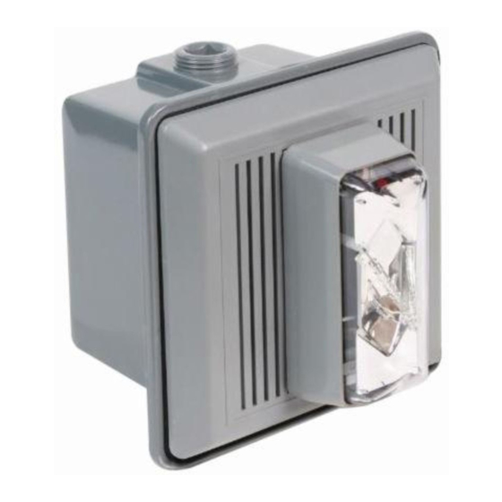
Electronic Horn/Strobe Signal Appliances
Installation Sheet
EN FR
EN: Installation Sheet
Description
The horn/strobes are high quality signals intended for use in
general signaling applications. The strobes flash at 1 fps
across their full operating voltage range.
It is recommended that these products be installed in
accordance with the requirements in the latest edition of
national and local electrical codes.
See Table 2 and Figure 1 for specifications.
Table 1: Electronic horn/strobes
Catalog number
Description
867STR(*)-**
Horn/Strobe, Surface Mount Indoor, Gray
868STR(*)-**
Horn/Strobe, Surface Mount Outdoor, Gray
869STR(*)-**
Horn/Strobe, Flush or Panel Mount Indoor, Gray
*
Insert lens color: C = Clear, R = Red, G = Green, B = Blue or A =
Amber.
**
The horns are available in two voltages. Insert suffix as required:
N5 = 120V AC, AQ = 24V AC/DC
Installation
WARNINGS
•
To reduce the risk of shock, do not connect AC or battery
power to the horn until directed in these instructions.
•
To reduce the risk of shock, do not tamper with this device
when the signal circuit is energized. Disconnect all power
and wait 5 minutes for stored energy to dissipate before
handling.
1.
Select a mounting method as detailed in Figure 1 and
install the electrical box using suitable hardware.
a.
For outdoor applications, install the weatherproof box
using four #10 x 1 1/4" (32 mm) screws and caplugs
provided in the enclosed parts bag. Carefully adhere
the gasket, part number P-007549-0082 (provided in
the enclosed parts bag) to the box as shown in
Figure 1.
© 2013 UTC Fire & Security. All rights reserved.
Notes
•
Be sure hook flange is facing outward as shown in
Figure 1.
•
The designation "TOP" on boxes denotes orientation
of box after installation.
2.
Attach mounting plate using two #8-32 screws provided
with the surface box or four #8-32 screws provided with
weatherproof box. The flush box uses two #8-32 screws
(not provided).
3.
Bring signaling circuit field wiring into electrical box.
4.
Connect signaling circuit field wires to terminals on
horn/strobe
assembly
5.
Ground in accordance with national and local electrical
codes. A green ground screw is provided with both the
indoor and outdoor surface boxes.
6.
Mount the horn/strobe assembly on the mounting plate
(Figure 1).
a.
The inside of the top of the grille has hinges that pass
through cutouts and engage with tabs on the
mounting plate. With the bottom of the grille lifted out
slightly, place the grille over the mounting plate so
that the hinges of the grille are in the mounting
cutouts.
b.
Properly seat the grille by pressing the bottom in.
c.
Fasten the bottom of the grille to the mounting plate
by installing the captive combination drive screw.
7.
Apply power and activate the horn/strobe unit to verify that
it is operating properly.
Maintenance
Should the unit fail to operate properly, do not
Caution:
attempt repair. Contact the supplier for replacement.
Perform a visual inspection and an operational test twice a
year.
1 / 6
P/N P-047550-1786 • REV 06 • REB 12FEB13
(Figure 2
through
Figure
4).
Advertisement
Table of Contents

Subscribe to Our Youtube Channel
Related Manuals for Edwards Signaling 867STR Series


Summary of Contents for Edwards Signaling 867STR Series
- Page 1 Electronic Horn/Strobe Signal Appliances Installation Sheet EN FR Notes • Be sure hook flange is facing outward as shown in EN: Installation Sheet Figure 1. • The designation "TOP" on boxes denotes orientation of box after installation. Description Attach mounting plate using two #8-32 screws provided The horn/strobes are high quality signals intended for use in with the surface box or four #8-32 screws provided with general signaling applications.
- Page 2 Figure 1: Detailed view Figure 2: Wiring the horn and strobe on the same circuit 2 / 6 P/N P-047550-1786 • REV 06 • REB 12FEB13...
- Page 3 Figure 3: Wiring the horn and strobe on different circuits Cat. Nos. 867STR(*)-AQ, 868STR(*)-AQ and Figure 4: Wiring the horn and strobe on different circuits Note: 869STR(*)-AQ potentially generate timing signals or pulses above 9 kHz and therefore have been tested and found to comply with the limits for a Class A digital device, pursuant to Part 15 of the FCC Rules.
- Page 4 sur la plaque de montage de façon à ce que ses Tableau 1: Klaxon/stroboscopes charnières s’engagent dans les fentes de la plaque de Cat. Description montage. 67STR(*)-** Klaxon/stroboscope, gris, montage en saillie à Appuyez sur le bas de le grille pour la mettre en l'intérieur place.
- Page 5 Figure 1: Vue détaillée Figure 2: Raccordement du klaxon et du stroboscope sur le même circuit P/N P-047550-1786 • REV 06 • REB 12FEB13 5 / 6...
- Page 6 Figure 3: Raccordement du klaxon et du stroboscope sur des circuits différents Figure 4: Bornier Les modèles 867STR(*)-AQ, 868STRC-AQ et Remarque : 869STR(*)-AQ peuvent générer des signaux ou des impulsions de plus de 9 kHz et ont de ce fait subi des essais prouvant leur conformité...
Need help?
Do you have a question about the 867STR Series and is the answer not in the manual?
Questions and answers