Advertisement
Quick Links
Advertisement

Related Manuals for CORNFIELD ELECTRONICS ArduTouch

Summary of Contents for CORNFIELD ELECTRONICS ArduTouch
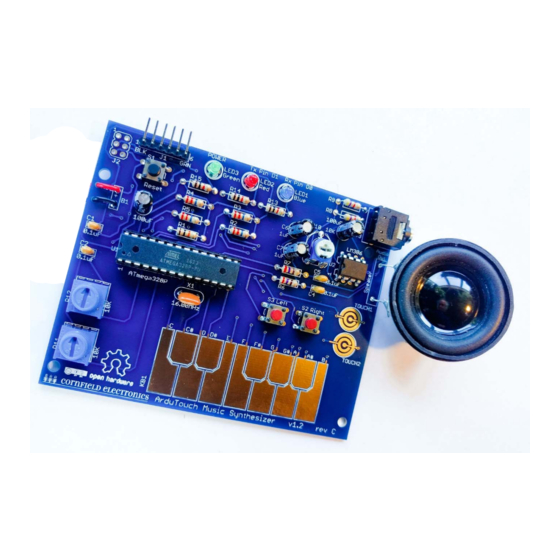
- Page 1 ArduTouch Music Synthesizer Assembly Instructions 27-Feb-2019...
- Page 2 The following photos will show you how to solder. But feel free to download the “Soldering Is Easy” comic book for free!
- Page 8 Some parts are inside of this battery pack All of the parts...
- Page 9 The board we’ll solder the parts to...
- Page 10 The tools you’ll need: • soldering Iron (35W or less) • solder (60/40 Sn/Pb, rosin core, 0.031” diameter or less) • soldering iron stand • cellulose kitchen sponge (not plastic!) • small wire cutter...
- Page 11 R1 – this is where it goes...
- Page 12 R1: Brown, Black, Orange (not Brown, Black, Red)
- Page 14 wires coming out from parts are called “leads” – they lead to the part...
- Page 15 R1 – this is how it will look before inserting it into the board...
- Page 16 these are pads...
- Page 19 R1 – inserted into the board...
- Page 20 How to hold a soldering iron (Like a pencil – held from underneath)
- Page 21 The perfect kind of solder for electronics: 60/40 rosin core, 0.031” diameter (or smaller) Important: Use solder WITH lead (Pb) !! Unleaded solder has very poisonous fumes!
- Page 22 3 Safety Tips…...
-
Page 23: Safety Tip
Safety Tip #1: Hot !! (When you touch the tip, you will let go quickly every time!) - Page 24 Safety Tip #2: Lead (Pb) is toxic But it easily washes off your hands with soap and water...
- Page 25 Safety Tip #3: (coming soon)
- Page 26 2 secrets to good soldering…...
- Page 27 Secret #1: Clean the tip! (before every solder connection) Bang (lightly) 3 times, Swipe, Rotate, Swipe: Keep the tip shiny silver!
- Page 30 Make sure solder melts on the underside of the soldering iron (not the side or top of the soldering iron tip)!
- Page 32 Secret #2: Keep hot tip down 1 second for solder to flow !!
- Page 34 If you can see any of the pad, or the hole, you need more solder – so, just do all the steps again to make it perfect.
- Page 35 Cutting with the tip of the wire cutter gives you more control...
- Page 36 Safety Tip #3: Hold or cover the lead ! (or it will fly into your eye!)
- Page 37 No wire sticking out...
- Page 38 soldered to the board Notice that: • each connection is a small bump (not flat) • you cannot see any pad (it’s totally covered with solder) • you cannot see the hole (it’s totally covered with solder)
- Page 39 One part at a time...
- Page 40 Till all the parts are soldered...
- Page 41 And it will look like this when you’re done.
-
Page 42: Let's Start
Let’s start! - Page 43 If you haven’t done so already, solder R1: brown, black, orange...
- Page 44 10K: Brown, Black, Orange R2, R3, R4, R5: 22M: Red, Red, Blue R6, R7: 270: Red, Violet, Brown R8, R9: 4.7K: Yellow, Violet, Red R13, R14, R15: Brown, Black, Red...
- Page 45 U1: microcontroller socket proper orientation...
- Page 46 U1: microcontroller socket: inserted correctly...
- Page 47 U1: microcontroller socket bend pins down on two corners, and solder all 28 leads to the board...
- Page 48 U1: microcontroller socket All 28 leads soldered to the board: Notice that each has a little bump of solder (not flat). ...
- Page 49 C1, C2, C4, C5...
- Page 50 C3, C8: 100uF...
- Page 51 C6, C7: 1uF...
- Page 52 C3, C8: 100uF...
- Page 53 C3, C8: Long Lead “+”...
- Page 54 C3, C8: 100uF – soldered to board...
- Page 55 C6, C7:...
- Page 56 C6, C7: Long Lead “+”...
- Page 57 C6, C7: 1uF – soldered to board...
- Page 58 LED1, LED2, LED3: Long Lead “+” We’ll use them for the speaker...
- Page 59 LED1, LED2, LED3 Green, Red, Blue – soldered to board...
- Page 60 long leads short leads...
- Page 61 Short leads into board short leads go into the board long leads sticking out from board...
- Page 63 S1: black Reset button Note: The color of this switch is not important (some kits may have different colors).
- Page 64 S2, S3: Red buttons Note: The color of these switches is not important (some kits may have different colors).
- Page 65 The orientation of X1 does not matter. Note: X1 may be yellow or blue.
- Page 66 Indented black dot Pin 1 Note: Your chip may be marked differently, but “386” will be printed on it somewhere. Note: Your chip may or may not have the indented half-moon at the left, it may have a black indented dot at the lower-left corner showing Pin 1.
- Page 67 When chips are new, their pins are bent out.
- Page 68 We need the pins bent straight and parallel. Use your work table to (gently) bend the leads.
- Page 69 Gently bend leads so they’re straight and parallel...
- Page 70 proper orientation U2: audio amp chip...
- Page 71 U2: inserted correctly...
- Page 72 bend pins down on two corners, and solder all 8 leads to the board...
- Page 73 U2 – soldered to board...
- Page 74 R10: volume control When new, the pins point straight down.
- Page 75 R10: volume control We need to bend them out a little to fit into the board.
- Page 76 R10: volume control If necessary, rotate the white top so that it looks like this photo (rotated half-way)
- Page 77 J3: headphone / output jack...
- Page 78 U1: microcontroller...
- Page 79 When chips are new, their pins are bent out. Note: Your kit’s U1 chip may or may not have its pins already bent straight and parallel. If not, you need to bend them, as shown in the next picture.
- Page 80 Note: Your kit’s U1 chip may or may not have its pins already bent straight and parallel. If not, you need to bend them, as shown in this picture. We need the pins bent straight and parallel. Use your work table to (gently) bend the leads.
- Page 81 U1: microcontroller These pins must be straight and parallel...
- Page 82 proper orientation U1: microcontroller...
- Page 83 U1: microcontroller make sure each pins rests in its hole in the socket with the proper orientation...
- Page 84 Use two thumbs to push microcontroller into the socket Make sure all 28 pins are in place, and push it into its socket. (This is actually way easier with 2 thumbs.) U1: microcontroller...
- Page 85 U1: microcontroller Inspect all pins, and be sure each went into its hole in the socket – not bent. If any pins are bent, (gently) pry out chip, straighten pins, and insert again.
- Page 86 R11 & R12: potentiometers...
- Page 87 R11 & R12: potentiometers...
- Page 88 Speaker...
- Page 89 Some kits have a speaker that looks like this Speaker...
- Page 90 We’ll add leads to the speaker from the LEDs Speaker...
- Page 91 Tin one side of each lead (i.e., cover with thin film of melted solder) Speaker...
- Page 92 Solder one lead to speaker Notice the correct place to solder the wire Speaker...
- Page 93 Solder next lead to speaker Notice the correct place Speaker to solder the wire...
- Page 94 Some kits have a speaker that looks like this Notice the correct place to solder the wires Speaker...
- Page 95 Insert speaker into board and solder both leads to board. Speaker...
-
Page 96: Battery Pack
Note: Some battery pack wires have thicker red and black plastic coatings. If so, you can widen the these two holes by gently rotating a scissors or small knife or small Phillips screwdreiver on the top and bottom of these two holes. - Page 97 Loop one lead into its pad, and solder. Then loop the other lead into its pad, and solder. Battery pack...
- Page 98 Done!
- Page 99 Let’s make noise!
- Page 100 Let’s make noise! Your ArduTouch comes pre-programmed with a really cool synthesizer, called “Thick”. “Thick” plays 4 sawtooth waves at once. • the left and right buttons change octaves • long press the left and right buttons to change sounds •...
- Page 101 Let’s make noise! Your ArduTouch comes pre-programmed with a really cool synthesizer, called “Thick”. If you are happy playing with “Thick” then no need to re-program But if you want to your ArduTouch. program other synths into your ArduTouch, the next pages show you how…...
- Page 102 We have written several way cool synthesizers for ArduTouch! Each is unique, and each way different than the others. To program in a new synth in your ArduTouch, you will need: • the Arduino software <http://arduino.cc> • a USB-Serial adapter cable (such as an FTDI, or equivalent) a nice one is available at <https://cornfieldelectronics.com/cfe/products/buy.php?productId=usbcable>...
- Page 103 Arduino Arduino is a very powerful tool! But it is very easy to use. It was designed for total beginners to use successfully. I won’t give a complete tutorial here – just some basics. For more info, there are many good Arduino tutorials online. A good place to start is: <https://www.arduino.cc/en/Tutorial/HomePage>...
- Page 104 Arduino First: Download and install the Arduino software < http://arduino.cc >...
- Page 105 Re-programming the ArduTouch Second: Download and install the ArduTouch Arduino library <http://cornfieldelectronics.com/cfe/projects.php#ardutouch> Instructions for installing a .zip library are at: < https://www.arduino.cc/en/Guide/Libraries> Scroll down till you see the section: “Importing a .zip Library“...
- Page 106 Re-programming the ArduTouch Third: Download ArduTouch synth sketches <http://cornfieldelectronics.com/cfe/projects.php#ardutouch> Store them on your computer anywhere you like.
- Page 107 Connecting your ArduTouch to your computer USB-Serial adapter cable Ones available from Cornfield Electronics look like this: <https://cornfieldelectronics.com/cfe/products/buy.php?productId=usbcable>...
- Page 108 Connecting your ArduTouch to your computer USB-Serial adapter cable Ones available from Cornfield Electronics look like this: <https://cornfieldelectronics.com/cfe/products/buy.php?productId=usbcable> You will need to download and install a driver for your Operating System (Windows, MacOS, or Linux): <https://www.silabs.com/products/development-tools/software/usb-to-uart-bridge-vcp-drivers>...
- Page 109 Connecting your ArduTouch to your computer IMPORTANT: Make sure the battery pack on your ArduTouch is OFF...
- Page 110 Arduino After you download and install the Arduino software start it, and you will see a screen that looks like this:...
- Page 111 Arduino The first time you start your Arduino software you need to do two things to set things up Choose “Genuino Uno” as the Board (Your ArduTouch board acts just like Arduino Uno board)
- Page 112 Arduino The first time you start your Arduino software you need to do two things to set things up Choose the Port (this will be different depending on your Operating System) (After installing the driver for your USB-Serial cable, with your USB-Serial cable plugged in, your operating system will see a serial port...
- Page 113 Arduino Your Arduino software is now ready to program your ArduTouch!
- Page 114 Arduino You can open an ArduTouch synth sketch from: File Open… (I opened “Arpology here)
- Page 115 Arduino With the USB-Serial cable connected to your ArduTouch board press the Upload button...
- Page 116 Arduino While uploading, you will see a progress bar… …and when it’s completed successfully, it says: “Upload done”...
- Page 117 ArduTouch Disconnect your ArduTouch board from the USB-Serial cable, turn on your battery pack, And…...
- Page 118 Let’s make new noise!
Need help?
Do you have a question about the ArduTouch and is the answer not in the manual?
Questions and answers