Table of Contents
Advertisement
Quick Links
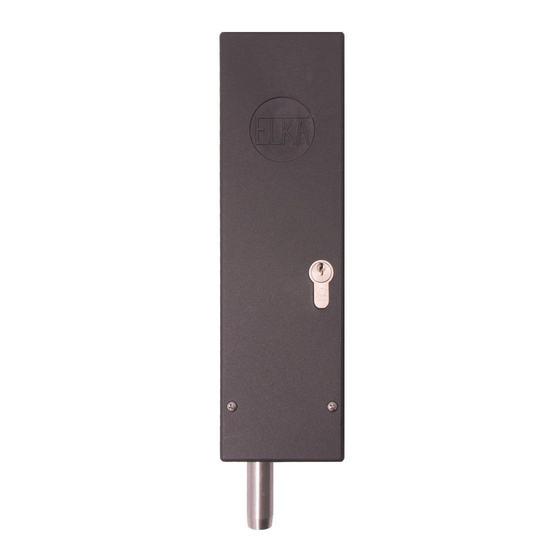
1. Usage
Electromagnetic bolt E 205 to lock swing gates. The bolt locks either downwards or to the
side.
2. Technical data
Power supply
Emergency release
Maximum current
Stroke
Measurements (W/H/L)
Degree of protection
Installation and Operating
Instructions
Electromagnetic Bolt E 205
24 Vac (Alternating current)
With key (cylinder lock)
approx. 6,0 A during stroke movement
approx. 1,0 A during stop position
50mm
58 x 295 x 94mm
IP 44
Advertisement
Table of Contents

Related Manuals for Elka E 205


Summary of Contents for Elka E 205
- Page 1 Installation and Operating Instructions Electromagnetic Bolt E 205 1. Usage Electromagnetic bolt E 205 to lock swing gates. The bolt locks either downwards or to the side. 2. Technical data Power supply 24 Vac (Alternating current) Emergency release With key (cylinder lock) Maximum current approx.
- Page 2 MO 36 LERN AMPEL Connect the electromagnetic bolt E 205 to the transformer clamp of the main board (secondary winding of the toroid transformer). The supply of the toroid transformer is switched over one conductor of the warning light connection.
- Page 3 AMPEL warning light Connect the electromagnetic bolt E 205 to the transformer clamp of the main board (secondary wiring of the toroid transformer). The supply of the toroid transformer is switched over one conductor of the warning light connection. Please set the pre-warning time for both directions to 4 seconds (learning sequence P8).
- Page 4 With other controllers the power supply has to come through a separate transformer from a connection, which is activated at every gate movement, e.g. warning light connection. Installation example controller MO34 transformer for E 205 PE N warning light © 05.10.2005 ELKA-Torantriebe GmbH u. Co. Betriebs KG Page 4 Electromagnetic bolt E 205...
- Page 5 4. Installation measurements Locking downwards. The length of the pin is 50mm from the lower end of the electromagnetic bolt. © 05.10.2005 ELKA-Torantriebe GmbH u. Co. Betriebs KG Page 5 Electromagnetic bolt E 205...
- Page 6 The operation of the system within CEN countries must also be conformant with the European safety-relevant directives and standards. We reserve the right to make technical improvements without prior notice. des Fortschritts vorbehalten © 05.10.2005 ELKA-Torantriebe GmbH u. Co. Betriebs KG Page 6 Electromagnetic bolt E 205...
Need help?
Do you have a question about the E 205 and is the answer not in the manual?
Questions and answers