Table of Contents
Advertisement
Quick Links
Advertisement
Table of Contents

Related Manuals for Sunstream Swiftshield SS-AMU13110-FL6B

Summary of Contents for Sunstream Swiftshield SS-AMU13110-FL6B
- Page 1 For: Sunstream FloatLifts™ A-SERIES UNIVERSAL SS-AMU13110-FL6B SS-AMU13124 FloatLift™ SS-AMU13124-FL10B ASSEMBLY, INSTALLATION AND USE MANUAL READ CAREFULLY BEFORE ASSEMBLY AND USE. KEEP THESE INSTRUCTIONS. COPYRIGHT 2017 SUNSTREAM CORPORATION® - ALL RIGHTS RESERVED FORM NO. 660868 Rev B PAGE 1...
-
Page 2: Table Of Contents
If you are not an authorized SunStream® Dealer and are not a reasonably-skilled mechanic, please contact SunStream® so that we can refer you to a local dealer who can skillfully and safely perform the assembly and installation of your SunStream® boatlift. It is the potential installer and/or assembler’s responsibility to determine whether he or she has the necessary... -
Page 3: Safety Instructions
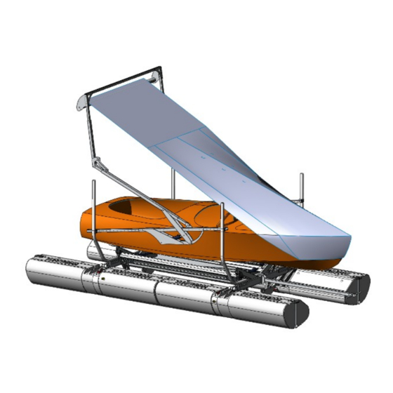
IMPORTANT SAFETY INSTRUCTIONS If you have any questions, please call your dealer, or SunStream® at (253)395-0500 Save These Instructions Your safety and the safety of others is very important. Proper use of the information in this manual will help avoid potential hazards that could cause damage to property and/or personal injury. - Page 4 SwiftShield™ Overview Cross Bar Roller Tube Fin Plate SwiftShield™ Cover Upper Arm Guide Post Cover FloatLift™ Mechanism Bow Sprit Cross Beam FORM NO. 660868 REV. B PAGE 4...
-
Page 5: Overview
SwiftShield™ Overview Continued Power Pack Box Battery RC Unit SunFluid Reservoir Hydraulic Pump Hydraulic Lines* from SwiftShield™ Cylinders *Lines shown disconnected FORM NO. 660868 REV. B PAGE 5... -
Page 6: Tools Required
Before beginning assembly, find a nice flat area with room to work and set up your parts. Read ahead to the installation procedure to determine the best location to start. Tools Required: SunStream® recommends the tools below for easier and quicker assembly. Box Knife (to open packaging) ... - Page 7 Positioning the boat too far forward, or too far aft could result in damage to the cover or the boat. ® To achieve a repeatable position of the boat on the lift, SunStream recommends using an indicator or reference point on the hull or rub rail of the boat to ensure re- peatable boat position.
-
Page 8: Bow Sprit
Assemble Bow Sprit Bow sprit extension Spreader tube Steps: 1. Install spreader tube before clamping bow sprit to frame. (Use wide spreader tube for pickle fork bow) 2. Lock in place with cotter pins. 3. Insert bow sprit extension into bow sprit. 4. - Page 9 Clamp Bow Sprit to forward crossbeam Steps: 1. Mount bow sprit on forward cross beam, between the bunks. 2. Apply anti-seize to bolt threads before installing nuts. 3. Center bow sprit on crossbeam, clamp in place with 4 bolts and nuts. 4.
- Page 10 FL10 Confirm (4) Guides Steps: 1. Confirm FL10 FloatLift™ has (4) Guides. 2. Mount guides in the widest position on FL10. For FL10 see manual 690188, Page 21 FL10 Guide Position FORM NO. 660868 REV. B PAGE 10...
- Page 11 FL6 Confirm (4) Guides (Continued) Steps: 1. Confirm FL6 FloatLift™ has (4) Guides. 2. Mount guides in the widest position on FL6. FL6 may need to drill additional hole - see drawing 942282 FL6 Guide Position NOTE: For FL6 Only - Install plastic roller casting guards at each Guide, and “First Stage Strap”...
- Page 12 Side Rail Clamps Steps: 1. Orient clamp with decal with “FL10” or “FL6” pointing up depending on which lift you are using. 2. Slide clamp over vertical guide tube with opening facing inboard. 3. For FL10 insert block into clamp, if block and plate not plumb, reverse the block. Insert bolts.
- Page 13 Install Side Rails with Side Rail Clamps Steps: 1. ABC-U Mechanism is installed inboard of guides. 2. For FL10 Locate aft clamp 45.5” from top of guide. Locate forward clamp 31.5” from top of guide. 3. For FL6 Locate aft clamp 44” above float. Locate forward clamp 54” above float. * This can be adjusted later if needed.
- Page 14 Install Side Rails with Side Rail Clamps (Continued) Steps: 1. Unfold upper arm and insert pin in arm linkage. 2. Repeat on opposite side. FORM NO. 660868 REV. B PAGE 14...
- Page 15 Locate Midpoint of Boat Pinning the Cover Mechanism in place Cover Mechanism Steps: 1. Using a tape measure, determine overall length of the boat, including swim plat- form, if equipped. 2. Locate the midpoint between the bow and stern of the boat. 3.
- Page 16 Route Hydraulic Hoses Steps: 1. Loosely route hydraulic hoses down aft guides and across crossbeam of FloatLift™ . NOTE: Secure hydraulic hoses with cable ties at end of installation. FORM NO. 660868 REV. B PAGE 16...
- Page 17 Connecting Hydraulic lines to the Power Pack Battery RC Control Note: Power Pack Wiring removed for clarity. Steps: 1. Remove two grommets on back of power pack box, closest to battery. Place one on each hydraulic line coming from the SwiftShield cylinders.
- Page 18 Install Starboard Fin Plate Steps: 1. Apply anti-seize to all bolt threads before installing nuts. 2. Install fin plate, using nuts and bolts on starboard arm only. 3. Pin should point inboard and fin plate should point down when in the aft posi- tion.
- Page 19 Install Cross Beam Steps: 1. Apply anti-seize to all bolt threads before installing nuts. 2. Attach both ends of cross beam assembly to the arms as shown with nuts and bolts. 3. Properly torque all nuts on cross beam gussets. 4.
- Page 20 Adjust Arm Length Steps: 1. Hydraulically actuate arms back and forth to determine optimal length of arm and position of cover mechanism. 12”-14” 12”-14” 2. The roller should extend 12” to 14” beyond the furthest point on the bow, including anchor, if equipped.
- Page 21 Install Roller Assembly Steps: 1. Apply anti-seize to all bolt threads before installing nuts. 2. Insert starboard end of roller over pin on starboard fin plate. 3. Attach opposite end of roller to upper arm with nuts and bolts through fin plate on the port side as shown.
- Page 22 Step 3 Install and Adjust the Cover Slot in Roller Fin Plate Notch Steps: 1. Position SwiftShield™ arms and roller at a manageable height above swim step. 2. Loosely drape cover over the boat. 3. Locate the keder bead (bolt rope) sewn into the tail end of the cover. 4.
- Page 23 Center the Cover on the Roller Step: With a tape measure, center the SwiftShield™ cover on the roller, left to right. FORM NO. 660868 REV. B PAGE 23...
- Page 24 Fitting the Cover - Overview Mitt Add Elastic Guide Ropes Mitt - Catches the bow of the boat. Rub Rail Shoulders Shoulders - Should ’pop’ over rub rail as SwiftShield™ arm reaches full aft position. Notes: Tighten guide ropes to “pop” cover over rub rail shoulders. Loosen guide ropes to minimize “Mitt”...
- Page 25 Fitting the Cover over Bow Steps: 1. Activate SwiftShield™ arms forward, to 12 o’clock position (straight up). 2. Pull SwiftShield™ cover all the way forward and fit the “Mitt’ over bow of boat. Attach Guide Ropes Steps: 1. Feed guide ropes through holes in bow sprit pipe.
- Page 26 Optional Elastic Cord - Conventional Bow Locations with frequent cross wind, may prevent cover from catching Steps: Conventional bow: 1. Elastic cord from bow sprit is attached to the tab centered on front edge of cover. Mitt Elastic cord Guide Ropes FORM NO.
- Page 27 Elastic Cord - Pickle Fork Bow (Continued) Steps: Pickle Fork Bow: 1. Elastic cords are attached to the spreader bar on each side and goes through a loop on the guide ropes. 2. Elastic cords are then attached to tabs on outer edge of cover near the bow on each side of cover.
- Page 28 Tensioning the Roller Torque Table Roller Approximate Max Torque Length Revolutions ft-lbs 126” Steps: 1. With roller in aft position. 2. Locate 3/4” nut on port end of roller assembly. 3. Refer to decal on roller for proper torque value. Tension roller by applying torque specified on decal;...
-
Page 29: Removing The Cover
You may have to remove your cover from time to time for maintenance or if you live in an area prone to high wind storms. Please note the following wind guidelines re- garding your cover. 1. Sunstream recommends not operating the SwiftShield™ in winds above 25mph . ®... - Page 30 Removing the Cover 6. Actuate arms to aft position (cover boat) NOTE: Steps 7-10 can be completed with arms in forward position (uncovered) if dock access allows for it. 7. Using hands, continue to turn roller in clockwise direction until ratchet and pawl click.
- Page 31 Removing the Cover 8. Remove two nuts holding the ratcheting “shark fin” from the upper arm. 9. Using two or more people, pull roller off arms. (Caution “shark fin” may spin if spring has not released all torsion) Note: Roller shown overhung on arms. Roller is under-hung on the Universal A-Series.
-
Page 32: Quick Tips
Quick Tips 1. Inspect location - Review dock shape and lift position before starting. Inspect for any objects including pilings, bumpers, or structure that may interfere with SwiftShield™ arms. Also inspect for overhead clearance if moorage is covered. 2. Slip Width - If mooring in a slip, ensure the FloatLift does not interfere with the dock or pilings. -
Page 33: Maintenance
Maintenance Annual inspection Pins - Confirm no wear and cotter pin in place Cover - Inspect for wear or damage Structure Roller spins smoothly Arms are not bent or misaligned Welds are not cracked or broken ... -
Page 34: Troubleshooting
Troubleshooting Problem Solution Check power on RC box is on SwiftShield™ does not operate with manual switch on RC box Check battery voltage SwiftShield™ does not operate with Check that lift operates with manual switches on RC box key fob transmitter buttons. -
Page 35: Accessories
Accessories SS-CC Off Season Roller Cover - To protect boat cover when stored on roller. SS-PZ Zinc Kit for salt water applications Batteries and Chargers LA-B27 Deep Cycle Battery (12v) LA-CS12W Solar Charging Kit LA-CC5 Solar Regulator - For use with solar panel in high solar areas) LA-CA12 110v AC Charging Kit (12v) FORM NO. -
Page 36: Warranty
Warranty WARRANTY: SunStream Corporation (“Company”) warrants its Products for non-commercial and/or non- ® governmental use for a period of three (3)* years, in both fresh and salt water, to the original Purchaser (“Purchaser”) against manufacturing defects in all Product materials and workman-... - Page 37 Purchaser must find the source of this current and stop it, or change zincs more frequently. Sunstream Corporation ® 22149 68...
Need help?
Do you have a question about the Swiftshield SS-AMU13110-FL6B and is the answer not in the manual?
Questions and answers