Table of Contents
Advertisement
Advertisement
Table of Contents

Summary of Contents for Epson/Seiko SRC-320 Series
- Page 1 ROBOT CONTROLLER SRC-320 External E. STOP Rev.9 EM01OC897F...
- Page 3 ROBOT CONTROLLER SRC-320 Rev. 9 Copyright ©1995-2001 SEIKO EPSON CORPORATION. All rights reserved.
- Page 4 WARRANTY The robot and its optional parts are shipped to our customers only after being subjected to the strictest quality controls, tests and inspections to certify its compliance with our high performance standards. Product malfunctions resulting from normal handling or operation will be repaired free of charge during the normal warranty period.
- Page 5 SUPPLIERS Japan & Others SEIKO EPSON CORPORATION Okaya Plant No. 2 1-16-15, Daiei-cho Okaya-shi, Nagano-ken, 394-0025 Japan TEL: 81-266-23-0020 (switchboard) 81-266-24-2004 (direct) FAX: 81-266-24-2017 North & South EPSON AMERICA, INC. America Factory Automation/Robotics 18300 Central Avenue Carson, CA 90746 TEL: (562) 290-5900 FAX: (562) 290-5999...
- Page 6 Safety Precautions Please carefully read this manual and any other manuals before installing this robot system (and definitely before connecting cables). Keep this manual in a handy location for easy access at all times. This sign indicates that a danger of serious injury or death WARNING will exist if the instruction thereunder is not followed.
- Page 7 CAUTION Connect the interlock switch circuit to the “normally closed” safety door input terminal of the REMOTE1 connector on the rear panel of the controller. Failure to do so will result in improper robot operation. Connect the cable firmly. Do not put a heavy thing on the cable or bend it extremely.
- Page 8 Manuals 1. User’s manual A manual that gives a general description of robots. It describes such things as safety precautions, operating methods, teaching methods, programming methods, and file management. Please read user's manual first. 2. Manipulator manual A manual for the manipulator itself. The basic volume describes safety tips to be observed by the user prior to/in setting up the equipment.
- Page 9 FOREWORD This manual specifies matters that you need to know to use the controller SRC-320 which has PNP I/O and Remote board. Please thoroughly read this and other related manuals before using the equipment. In case that you need information about the SRC-320 which has NPN I/O and remote cir- cuit, please request the other manual to the service center.
- Page 10 The improvements at; Rev.3: New changes to the Emergency Stop Circuit to improve safety feature: The Emergency Stop Circuit which used to work on each robot cell basis, is now re- designed. The new change incorporates that an input from any emergency stop switch stops the entire system regardless of the power ON/OFF status on the RE- MOTE1 connector.
-
Page 11: Table Of Contents
TABLE OF CONTENTS Functions Volume Various combinations of controller settings and specifications ..... 2 1. Part Names and Functions ............3 1.1 Front panel..................... 3 1.2 Rear panel ..................... 5 1.3 Controller interior ................... 7 1.4 Safety features..................9 2. Installation ..................... - Page 12 10. Options ....................63 10.1 Option types and board current consumption......... 63 10.2 Additional I/O board ................ 64 10.3 Additional RAM ................65 10.4 Additional RS-232C board .............. 67 11. Specifications ................... 68 11.1 Standard specifications ..............68 11.2 Outer dimensions ................69 Maintenance Volume 1.
- Page 13 10. Regenerative Brake Unit (for EL, EH, BL, XM series) ... 121 11. Manipulator Operation Check ..........123 12. Cooling Fan ..................126 12.1 Fan inspection ................126 12.2 Fan replacement................127 13. Front Board ..................128 13.1 Front board inspection..............128 13.2 Front board replacement ..............
- Page 15 1.各部の名称 Functions The Functions volume describes the basic functions of the controller. Please refer to sections in this volume for safety features, connection to the other peripheral equipment and standard settings.
-
Page 16: Various Combinations Of Controller Settings And Specifications
Functions Various combinations of controller settings and specifications Various combinations of controller settings and specifications The various settings and the specifications of the controller are different depend on the ma- nipulator models. Therefore, be sure to connect the controller to the manipulator with the same M. -
Page 17: Part Names And Functions
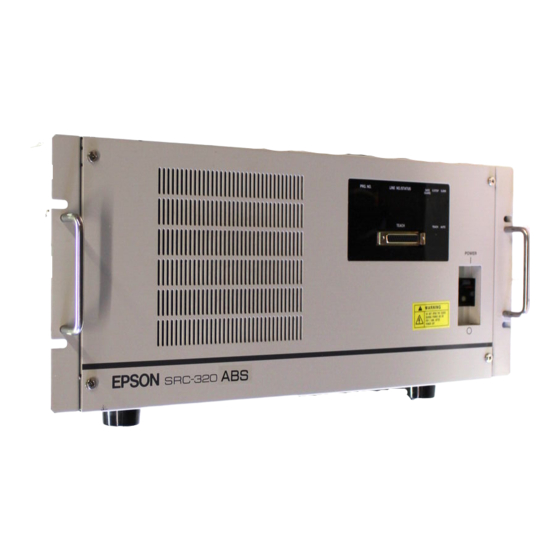
Functions 1. Part Names and Functions 1. Part Names and Functions 1.1 Front panel ③ ④ ⑥ ⑥ ⑤ ⑦ ⑦ ⑥ ⑥ ② ① ① POWER switch Controller power switch. There are a leakage indication button (yellow) and a test button (red) at right of the controller power switch. - Page 18 Functions 1. Part Names and Functions ④ LINE NO./STATUS LED When a program is being executed, this shows the line number of the program being exe- cuted. When an error occurs, the error number is shown. ⑤ Indicator panel LED The individual LEDs show the following information.
-
Page 19: Rear Panel
Functions 1. Part Names and Functions 1.2 Rear panel ⑩ ⑨ ④ ⑥ ⑫ ⑦ ⑬ ⑭ ⑪ ⑧ ① ⑤ ③ ② ① POWER cable Cable for controller AC power. It is composed of two power leads (brown, blue) and an earth lead (green/yellow). ②... - Page 20 Functions 1. Part Names and Functions ⑦ M/C SIGNAL This is a connector for signals from such things as the robot motor encoder or calibration sensor. Connect the signal cable attached to the manipulator. ⑧ M/C POWER Connector for robot power source. Connect the power cable attached to the manipulator. ⑨...
-
Page 21: Controller Interior
Functions 1. Part Names and Functions 1.3 Controller interior The interior of the controller as it appears after removal of the front panel is shown in the figure below. Please do not pull hard when removing the front panel. A cooling fan and the indicator panel are attached to the front panel and connected to the interior by cables. - Page 22 Functions 1. Part Names and Functions ① MPU board and mounting bracket This board, containing the CPU, forms the nucleus of the controller and controls the vari- ous interfaces and executes the programs. It has DIP switches SD1 and SD2. The MPU board and the mounting bracket are one piece, and the main body is fixed by the mounting bracket.
-
Page 23: Safety Features
Functions 1. Part Names and Functions 1.4 Safety features The robot is equipped with safety features that protect it and peripheral equipment. However, these features are strictly to guard against unforeseen circumstances. To ensure safety, it is very important that you implement the maintenance inspections described in Maintenance volume of this manual and manipulator manual, and that you use the robot correctly. - Page 24 Functions 1. Part Names and Functions Dynamic brake Dynamic brake circuit consists of a relay that switches the connection of motor power line to make a short-circuit on the motor side or to connect to the AC servo driver. When emergency stop is input, or the following malfunction is detected, the dynamic brake activates and stops the rotation of motor.
-
Page 25: Installation
Functions 2. Installation 2. Installation The controller SRC-320 is not designed for the use in clean room environments. If you NOTE use the controller in the clean room, take an adequate countermeasure. As an example, place the controller in a box having a cooling or an exhausting mechanism. 2.1 Unpacking The controller weighs 24kg (standard). -
Page 26: Environmental Requirements
Functions 2. Installation 2.2 Environmental requirements In order to maximize the functions of the SRC-320 controller and to use it in a safe manner, an appropriate environment is necessary. Please place the controller in an environment which satisfies the following conditions. Ambient temperature 5 to 40°C (with minimal variation) -
Page 27: Vertical Placement
Functions 2. Installation 2.3 Vertical placement Standard controller placement is horizontal. In the event that vertical placement is un- avoidable, please do so following the points below. 1) Use the left side as the new bottom (see figure below). 2) Remove the four legs mounted on the original bottom. Remove them by inserting a flat screwdriver between the bottom and the legs. -
Page 28: Power
Functions 2. Installation 2.4 Power Power specifications Please be sure available power meets the following specifications. AC 200 to 230V ±10% Voltage Phase Single phase Frequency 50/60Hz The controller itself consumes a maximum of approximately 200W, but actual consumption depends on the manipulator motors. Please Power refer to the manipulator manual for manipulator power consumption consumption... - Page 29 Functions 2. Installation For reference, specifications of the AC power cable included with the controller appear below. Item Specification Components 41 wires/ 0.26 mm (AWG #14) Conductor Outer diameter 1.9 mm (typical) Color Brown, blue (AC power), green/yellow (ground) Insulator Outer diameter 3.5 mm (typical) UL.
-
Page 30: Cable Connections
Functions 2. Installation 2.5 Cable connections Be certain that the power has been turned off controller power before you plug WARNING or unplug any of the cables linking the manipulator and controller. Failure to do so could cause electrification and malfunction. When installing the cable between the manipulator and the controller, make CAUTION sure the M. - Page 31 Functions 2. Installation ② M/C signal cable Cables with 68-pin, square connectors on both ends. Connect the signal cable to the manipulator SIGNAL connector and controller M/C SIG- NAL, respectively. Using the two fitting screws attached to the connectors, tighten down the connectors so that they will not come loose.
- Page 32 Functions 2. Installation ⑦ I/O-1 If you have input/output units, connect them to this connector. The details regarding I/Os appear in “6. I/Os” in this volume, and details regarding RE- MOTE3 appear in “7. I/O Remote Set Up” in this volume. ⑧...
-
Page 33: Noise Countermeasures
Functions 2. Installation 2.6 Noise countermeasures Please pay attention to the following points when wiring the system. To ground the controller chassis is very important not only for prevention from electric shock, but also for reducing the electric noise influence around the controller. There- fore, be sure to connect the yellow/green wire in the power cable of the controller to the earth terminal of the factory power supply. - Page 34 Functions 2. Installation For such induction elements as relays and solenoid valves connected to an I/O, be sure to use elements which have surge suppressors. If surge suppressors are not used, in- sert an element such as a rectifying diode as close as possible to the inductors, as shown below.
-
Page 35: Teach Port
Functions 3. TEACH Port 3. TEACH Port This port is used for such tasks as programming, teaching, and debugging, and is connected to a personal computer or teaching pendant TP-320 (option). This port becomes a con- sole port when in the TEACH mode. If nothing is connected to the TEACH port, the robot will enter the emergency stop condi- tion. -
Page 36: Teaching Pendant Tp-320 Connection
Functions 3. TEACH Port 3.2 Teaching pendant TP-320 connection Teaching operation is possible to be done with a handy teaching pendant TP-320 instead with a personal computer. TP-320 is employing both of an emergency stop switch (nor- mally closed) and an enable switch (normally open). The dedicated cable for the control- ler is attached to TP-320. -
Page 37: Pin Assignment Of Teach Port
Functions 3. TEACH Port 3.4 Pin assignment of TEACH port The pin assignment for the TEACH port is as shown below. Pin number Signal name TEACH E. STOP input (normally closed) DMSW input (normally open) (enable switch input) If you prefer to use your own connection cable, please use a shielded cable and use the following example wiring diagram as a reference for wiring your cable. -
Page 38: Remote1
Functions 4. REMOTE1 4. REMOTE1 Be sure to operate the system with a functional interlock switch on the safe- WARNING guard. It is dangerous to operate the system with the switch wound in tape, or without the on/off conditions since the safeguard input functions will not operate. -
Page 39: Connecting To Remote1 The Safeguard Switch And Emergensy
Functions 4. REMOTE1 4.1 Connecting to REMOTE1 the safeguard switch and emergency stop switch Use emergency stop switch conformed to the related safety standards (EN418, CAUTION EN60204-1). The interlock switch must be designed and installed such as the contacts are opened by force when the safeguard opens, not by spring of the switch itself. - Page 40 Functions 4. REMOTE1 Use an interlock switch that opens when the safeguard opens. The safeguard input func- tions when the safeguard input terminals open, and activates the low power state. A power source should be connected to pin #10 (or #11) and #23 (or #24) for the interlock switch.
-
Page 41: Safeguard Input Functions
Functions 4. REMOTE1 4.2 Safeguard input functions The basic function of the safeguard input is to increase safety by stopping the robot and regulating the motor output when the safeguard is opened. When the safeguard is opened/closed while the robot is running a program or is in the direct command condition, it will quickly pause and turn into the Low Power state. - Page 42 Functions 4. REMOTE1 In case of S. NET mode, commands execution (direct commands) except for motion com- mands is not affected by the safeguard. TEACH mode In TEACH mode it is possible to operate the robot regardless of whether the safeguard is opened or closed.
- Page 43 Functions 4. REMOTE1 The Low Power/High Power state selection differs as shown below based on the combina- tion of the safeguard status (open/closed) and power mode set by POWER command. POWER LOW (LP ON) POWER HIGH (LP OFF) Safeguard open Low power state Low power state Safeguard closed...
-
Page 44: Pin Assignment Of Remote1
Functions 4. REMOTE1 4.3 Pin assignment of REMOTE1 The pin assignment of the REMOTE1 connector is as shown below. Pins #12, 13 and #25, 26 are for user’s +24V power. This is the same as the CAUTION power on I/O, so please be careful of the power capacity. The pin #5 and #6 for an emergency stop circuit are both connected to the in- ternal +24V power from the controller. - Page 45 Functions 4. REMOTE1 *1 These are “normally closed” contacts which open upon the occurrence of a system error. By using the jumper pins on the REMOTE board, it is possible to output other condi- tions. Jumper pin Function when shorted outputs for emergency stop occurrence also outputs for error occurrence There is a possibility that there will be no output if the internal controller +24V power...
-
Page 46: Circuit Diagram And Example Wiring Of Remote1
Functions 4. REMOTE1 4.4 Circuit diagram and example wiring of REMOTE1 Input circuit Emergency stop input current 500mA max. Safeguard input current typical/for 24V input DC 12 to 24V ±10% Output circuit Rated output voltage Maximum output current 250mA/1 output Output driver Power MOS FET Saturation voltage... -
Page 47: Wiring Example For External Emergency Stop Circuit
Functions 4. REMOTE1 4.5 Wiring examples for external emergency stop circuit Please follow one of the following system configurations if you are extending an emer- gency stop circuit outside the controller. Connect an emergency stop circuit in a multiple robot system Please install a safety relay in an external emergency stop circuit as shown in the figure below. - Page 48 Functions 4. REMOTE1 Short-circuit between #6 and #19, and, #5 and #18 when an emergency stop circuit is not NOTE used. REMOTE1 +24 V +24 V output for emergency stop circuit Short-circuit Emergency stop output (to the + contact) E. stop switch of REMOTE2 (OPU) E.
-
Page 49: When Not Using The Operating Unit
Functions 5. When Not Using the Operating Unit 5. When Not Using the Operating Unit Connect the optional operating unit OPU-300 or OPU-320 to the REMOTE2 connector. If you do not connect the operating unit, then you need to connect the REMOTE2 connec- tor that came standard with the controller and take the following additional steps. - Page 50 Functions 5. When Not Using the Operating Unit Pin assignment REMOTE2 is a 20-pin connector, but only the pins in the table below can be used for wir- ing. Do not use any other pins under any circumstances, as they have not been freed for use.
-
Page 51: When Not Using The Operating Unit As A Console
Functions 5. When Not Using the Operating Unit 5.2 When not using the operating unit as the console The input port for controlling robot or the device connected to it is collectively referred to as the console. In many cases, operating unit is used as the console in AUTO mode. But when operating unit is not used, it is necessary to set up a console elsewhere. -
Page 52: I/O
Functions 6. I/O 6. I/O I/O links your input/output equipment. The controller comes standard with one I/O port on the rear panel, enabling you to use 16 inputs and 16 outputs. The cable connector for user cable is a standard accessory. If you install additional I/O boards, you can use 16 inputs and 16 outputs multiplied by the number of I/O boards. -
Page 53: Input Circuit
Functions 6. I/O 6.1 Input circuit DC 12 to 24V ±10% Input voltage range ON voltage DC 10.8V (min.) OFF voltage DC 4V (max.) Input current typical with input of DC 24V Input circuit diagram and wiring example I/O-1 GND +DC Input No. -
Page 54: Output Circuit
Functions 6. I/O 6.2 Output circuit DC 12 to 24V ±10% Rated output voltage Maximum output current 250mA/1 output Output driver P channel power MOS FET Saturation voltage 1.0V Output circuit diagram and example of connections I/O-1 GND +DC Output No. 0 Inductor Output No. -
Page 55: Customer Use Power Supply
Functions 6. I/O 6.3 Customer use power supply A power supply for customer use is supplied to each I/O connector. This power supply is used for all I/Os as well as for REMOTE1 and REMOTE2. The current capacitance is 1A. Do not use this internal power supply together with an external power source, as do- ing so causes controller failure. -
Page 56: I/O Remote Set Up (Remote3)
Functions 7. I/O Remote Set Up (REMOTE3) 7. I/O Remote Set Up (REMOTE3) You can set up a remote function in I/O-1 and use it as REMOTE3. You can use this as the console when in AUTO mode in place of operating unit OPU-300 or OPU-320 to im- plement various controls. -
Page 57: Remote3 Input/Output Signals
Functions 7. I/O Remote Set Up (REMOTE3) 7.2 REMOTE3 input/output signals The arrangement of signals that can be set up as REMOTE3 is shown in the table below. Input/output number has also been included in the table since you may also use them. Refer to the wiring examples in “6. - Page 58 Functions 7. I/O Remote Set Up (REMOTE3) REMOTE3 Input Signal Functions Signal Name Functions This signal is used for (1) initializing an error state; (2) inter- rupting a program. The robot controller will be reset at the input of this signal. If the robot controller needs to be reset during execution of a RESET program, make sure that the signals are input as follows:...
- Page 59 Functions 7. I/O Remote Set Up (REMOTE3) REMOTE3 Output Signal Functions Signal name Functions This signal is output when the robot controller is in the reset state. Make sure that this signal is being output and that the START output signal is NOT being output when the following signals RESET input to the REMOTE3: START, HOME, MOTOR ON, MOTOR OFF, MCAL and...
-
Page 60: Valid/Invalid Input Signals
Functions 7. I/O Remote Set Up (REMOTE3) 7.3 Valid/Invalid input signals The validity of input from REMOTE3 and operating unit OPU-300 or OPU-320 in each mode changes as shown below depending on such conditions as the setup of software switch SS1 and the console selection. In the case of REMOTE3, input is invalid if the remote has not been set up. - Page 61 Functions 7. I/O Remote Set Up (REMOTE3) In AUTO mode, when you use the CONSOLE command to select “OP” as the console, the AUTO mode remote which was specified by software switch SS1-1 is the console. All input from the Console is REMOTE3 or remote that was selected as the console is valid.
- Page 62 Functions 7. I/O Remote Set Up (REMOTE3) In AUTO mode, when you used the CONSOLE command to select either “#20” or “#21” AUTO mode of RS-232C as the console, the device connected to the port that you selected is the Console is RS-232C console.
-
Page 63: Timing Charts
Functions 7. I/O Remote Set Up (REMOTE3) 7.4 Timing charts Response timing for REMOTE3 input signals is basically as follows. Signals input from REMOTE1 and REMOTE2 are also shown. Input signal Input remote Safeguard input REMOTE1 AUTO mode input REMOTE2 TEACH mode input REMOTE2 Notes regarding input signals... - Page 64 Functions 7. I/O Remote Set Up (REMOTE3) The timing chart when power is turned ON Initialization inside the controller is finished and RESET output is turned ON 4.3 seconds after power is turned ON. From this point on, output from each remote is possible. Just before completion of initialization, RESET/START output turns ON/OFF momentarily.
- Page 65 Functions 7. I/O Remote Set Up (REMOTE3) Timing chart for motor power ON, etc. When RESET output is ON and the signals shown in the chart below are input, START output turns ON and RESET output turns OFF. After this input is executed, START out- put turns OFF and RESET output turns ON.
- Page 66 Functions 7. I/O Remote Set Up (REMOTE3) Timing chart for program execution START input RESET output turns OFF and START output turns ON 5ms after the input of START while at the RESET state. In case of specifying the program No. by binary code: Turn ON the Program No.
- Page 67 Functions 7. I/O Remote Set Up (REMOTE3) Timing chart for safeguard input Safeguard output turns ON 5ms after the input of Safeguard while at the START state. After 320ms, PAUSE output turns ON and START output turns OFF. The PAUSE state is maintained while the Safeguard input is ON (the “Safeguard open” is latched).
- Page 68 Functions 7. I/O Remote Set Up (REMOTE3) Timing chart for TEACH mode and AUTO mode Regardless of whether operating in TEACH mode or AUTO mode, if you switch modes during execution, there will be a pause and then the controller will be reset. The charts below show a switch to TEACH mode when AUTO mode was operating.
- Page 69 Functions 7. I/O Remote Set Up (REMOTE3) Timing chart for emergency stop Emergency Stop input can be input at any time. During the emergency stop state only RESET input for canceling the emergency stop can be input. Emergency Stop output turns ON 5ms after Emergency Stop is input. In 270ms, START output turns OFF and RESET output turns ON.
-
Page 70: Rs-232C
Functions 8. RS-232C 8. RS-232C The standard controller is equipped with 2-channel RS-232C so that you can connect pe- ripheral equipment or a host computer to the robot and perform data communications and centralized control. 8.1 Communications cable A communications cable is not supplied. Use 9-pin D-sub connector for the communications cable. - Page 71 Functions 8. RS-232C Wiring example A common wiring example is shown below. [Controller] [Connected equipment connector] Signal Pin No. Pin No. Signal Clamp hood The following example is for CS control. Because the controller does not perform RS control, it cannot control transmissions from the connected equipment.
-
Page 72: Communicatin Preparations
Functions 8. RS-232C 8.2 Communication preparations To communicate using the controller and connected equipment, it is necessary to make the communication method (configuration) of both RS-232C ports the same. You must use the CONFIG command to set the following: Transmission speed (baud rate) Character bit number Parity Stop bit number... -
Page 73: Switch Types And Jumper Pin Set Up
Functions 9. Switch Types and Jumper Pin Set Up 9. Switch Types and Jumper Pin Set Up Many settings are necessary to use the robot’s functions correctly. Here, we explain the settings of the MPU board's jumper pins and DIP switches as well as of software switches. You do not need to change the settings, as they have been correctly set at the factory on the basis of your specifications. -
Page 74: Software Switches
Functions 9. Switch Types and Jumper Pin Set Up 9.2 Software switches SD1 to 3 are hardware switches. Switches that you set using software are called “software switches.” Controller has six such software switches, SS1 to 6. You set them from a personal computer. -
Page 75: Mpu Board Jumper Pins
Functions 9. Switch Types and Jumper Pin Set Up Bit No. Function Range check of HOFS value Not performed Performed U coordinate conversion of LOCAL Teaching data coordinate command dependent value dependent (Reserved for system) (Always OFF) (Reserved for system) (Always OFF) (Reserved for system) (Always OFF) -
Page 76: Locations Of Dip Switches And Jumper Pins On Mpu Board
Functions 9. Switch Types and Jumper Pin Set Up 9.4 Locations of DIP switches and jumper pins on MPU board The position of the DIP switches and jumper pins (XP) on the MPU board are shown in the figure below. 1 2 3 4 5 6 7 8 Each DIP switch has bit levers. -
Page 77: Options
Functions 10. Options 10. Options The following options have their own manuals. Please see the each manual for details. Operating unit : OPU-300 or OPU-320 Teaching unit : TP-320 Programming support software : SPEL Editor : SPEL for Windows Pulse generating board (be installed in controller) Here, we explain the options that can be installed in the controller except above items. -
Page 78: Additional I/O Board
Functions 10. Options 10.2 Additional I/O board The standard controller has 16 I/Os, but you can increase this number up to 128 I/Os. Additional I/Os come in units of 16 (16 inputs/16 outputs). The following parts are re- quired for additional I/Os. Please make certain that you get all parts at the time of purchase. -
Page 79: Additional Ram
Functions 10. Options 10.3 Additional RAM Standard file memory is 100KByte. You can expand file memory to 1.1MByte by adding two RAM modules. You can also set DIP switches to expand main memory if you are unable to run a long program on the standard main memory alone. Follow the steps below when installing additional RAM. - Page 80 Functions 10. Options 7) Plug the jumper socket into jumper pin XP6. (Use one of 5 jumper sockets which are shipped with controller.) By this jumper socket, the additional RAM module will be backed up by battery. NOTE Do not disassemble other jumper pins. 8) Setting DIP switches Flip bit 1 of DIP switch SD2 on the MPU board to the ON position.
-
Page 81: Additional Rs-232C Board
Functions 10. Options 12) Restoring files Return the files that you backed up earlier to the controller. See SPEL Editor or SPEL for Windows manual for details. 10.4 Additional RS-232C board Two channels of RS-232C are on one board. Install the RS-232C simply by plugging the board into an option slot. -
Page 82: Specifications
Functions 11. Specifications 11. Specifications 11.1 Standard specifications Model name SRC-320 4 axis simultaneous software, AC servo control Speed control 1 to 100 % programmable Control method Accelera- 1 to 100 % programmable tion/Decel-eration Automatic acceleration control Positioning control Point-to-point control, Continuous path control 32 bits (68EC020) (Backed up by lithium battery) Memory media... -
Page 83: Outer Dimensions
Functions 11. Specifications 11.2 Outer dimensions (unit: mm) 4-φ30 23.5... - Page 84 Functions 11. Specifications...
- Page 85 Maintenance 1. Outline of Maintenance Maintenance The maintenance volume describes the maintenance procedure for each part in controller SRC-320.
-
Page 86: Outline Of Maintenance
Maintenance 1. Outline of Maintenance 1. Outline of Maintenance 1.1 Safety precautions on maintenance Please carefully read this manual and other related manuals before performing any routine maintenance. WARNING Only trained personnel should be allowed to operate, perform function testing, and maintain this robot and the robot system. -
Page 87: Maintenance Schedule And Inspections
Maintenance 1. Outline of Maintenance 1.2 Maintenance schedule and inspections Proper inspection steps are essential to prevent troubles and to maintain safety. This section describes maintenance inspection schedule and procedure, so be sure to do inspection as follows: Maintenance Inspection schedule Inspection procedure is divided into such five stages as daily, monthly, quarterly, biannu- ally and annually as each one is added. - Page 88 Maintenance 1. Outline of Maintenance Inspections Inspection while the power is OFF (Be sure to turn off the power.) Inspection item Point of inspection Daily Monthly Quarterly Biannual Annual Check looseness of External connectors ○ ○ ○ connectors. on controller. looseness Connectors on boards found, plug it in...
-
Page 89: Outline Of Structure
Maintenance 2. Outline of Structure 2. Outline of Structure 2.1 Fixing screws of panels Covers of a controller can be taken off by loosening the following screws: (1) Screws for upper cover : 4 pieces (2) Screws for front panel : 4 pieces (3) Screws for rear panel : 8 pieces Upper cover... -
Page 90: Location Of Parts
Maintenance 2. Outline of Structure 2.2 Location of parts PSU1, PSU2 Regenerative brake unit (for EL, EH, BL, XM3000 series) PSU3 Motor power unit MPU board Top view of interior AC servo driver for axis #2 AC servo driver for axis #3 I/O board REMOTE board Option slot... -
Page 91: Diagram Of Cable Connections
Maintenance 2. Outline of Structure 2.3 Diagram of cable connections RT3300 ES/EC BN/BNA... - Page 92 Maintenance 2. Outline of Structure EL/EH XM3000...
-
Page 93: Connector Pin Assignment
Maintenance 2. Outline of Structure 2.4 Connector pin assignment Rear panel Front panel M/C POWER (X2) M/C SIGNAL (X3) TEACH (X70) Cable side JL05-6A20-29PC-A66F0 DX30A-68P DB-25PF-N connector Controller side JL05-2A20-29SC-F0 DX20A-68S DB-25ST-N-S1 connector 2HOME ENC+5V ENC+5V E.STOP+ E.STOP- 4HOME ENC+5V ENC+5V DMSW+ DMSW-... - Page 94 Maintenance 2. Outline of Structure REMOTE board I/O board REMOTE1 REMOTE2 RS-232C #20 RS-232C #21 I/O-1 Cable side 10126-3000VE 10120-3000VE DE-9SF-N DE-9SF-N DB-50PF-N connector Controller side 10226-52A2JL 10220-52A2JL DESP-JB9P DESP-JB9P DB-50ST-N-S1 connector IN COM 0 26 OUT 7 S.ERR IN 0 SAFE IN 1 OUT 8...
-
Page 95: Main Power Supply Circuits
Maintenance 2. Outline of Structure 2.5 Main power supply circuits The main power supply circuit is comprised of an earth leakage circuit breaker, a noise fil- ter, a circuit that supplies 200 volts AC to the motor power unit and three PSUs (switching power supply unit) that supply +5V/±12V, +24V and user +24V power to the mother board. -
Page 96: Psu
Maintenance 3. PSU 3. PSU 3.1 PSU layout PSU2 PSU1 Regenerative brake unit (for EL, EH, BL, XM3000 series) PSU3 MPU board Motor power unit PSU comprises three switching power supplies (PSU1, PSU2, PSU3) that output the vari- ous voltages used inside the controller. The voltages output by each power supply are shown below. -
Page 97: Power Supplies From Psu
Maintenance 3. PSU 3.2 Power supplies from PSU PSU1 PSU2 PSU3 ±12V To be disconnected at: Internal User VCC +7V ENC -5V ±12V +24V +24V ○ ○ ○ ○ ○ ○ ○ PSU board Board ○ ○ ○ MPU board Board ○... -
Page 98: Psu Inspection
Maintenance 3. PSU 3.3 PSU inspection Only trained personnel should be allowed to perform the following operations. WARNING Trained personnel are those who have taken a robot training course (held by the dealer) or those who have carefully read the manuals and have equivalent knowledge or skill. - Page 99 Maintenance 3. PSU + side - side Where measured : standard (V) name from connector X42 at 31c and 32c 4.95 to 5.15 PSU1 board (see drawing at 30c and 29c 11.4 to 12.6 +12V below) at 28c and 29c -11.4 to -12.6 -12V connector X73 at 1 (red) and 2 (black)
- Page 100 Maintenance 3. PSU Check for PSU1 and the related devices If there is malfunction (short-circuit) somewhere in the +5V power circuit that is output from PSU1, the upper circuit protector will activate, and the “8A” button should come out. If there is malfunction (short-circuit) somewhere in the +12V power circuit, the lower cir- cuit protector will activate, and the “1A”...
- Page 101 Maintenance 3. PSU Check for PSU2, PSU3 and the related devices 1) Disconnect the X80 connector on regenerative brake unit and remove the regenerative EL/EH brake unit from the controller referring to “10. Regenerative Brake Unit” of this volume XM3000 when the manipulator is EL, EH, BL or XM3000 series.
- Page 102 Maintenance 3. PSU 5) If the Error #110 (“the error at PSU2”) occurs, disconnect all the parts/equipment whose power is supplied from PSU2. The previous table, “Power supplies from PSU,” list all such parts. Refer to the described method of disconnecting for replac- ing each part.
-
Page 103: Psu Replacement
Maintenance 3. PSU 3.4 PSU replacement If the AC input voltage is normal while the DC output voltage is out of the normal range, replace the PSU in question by following the steps below. Only trained personnel should be allowed to perform the following operations. WARNING Trained personnel are those who have taken a robot training course (held by the dealer) or those who have carefully read the manuals and have equivalent... - Page 104 Maintenance 3. PSU PSU1, PSU2 replacement 1) Turn OFF the controller, unplug the controller’s power cord and wait about two min- utes. 2) Remove the controller’s upper cover. As the earth line is connected to the upper cover, do not pull the cover unnecessarily. 3) Cut off the cable clamp which fastens the cable to PSU cover.
- Page 105 Maintenance 3. PSU PSU3 replacement 1) Turn OFF the controller, unplug the controller’s power cord and wait about two min- utes. 2) Remove the controller’s front panel. As various cables are connected to the front panel, do not pull the panel unnecessarily. 3) Disconnect the earth line and the two connectors X71 and X73 from the back side of the front panel.
- Page 106 Maintenance 3. PSU 7) Loosen two screws fixing PSU3 at the left panel of the controller and pull out PSU3 from the controller. PSU3 8) Insert a new PSU3 in the controller, and install it on the left panel of the controller. 9) Connect the connector X15 and X16 to PSU3.
-
Page 107: Psu Board
Maintenance 4. PSU Board 4. PSU board 4.1 Layout and function of PSU board parts The PSU board outputs and monitors the power supplies that are used by the controller, manipulator and other peripheral equipment. SKP327 PSU BOARD Handle (1) Fuse (F1) A 2A fuse for over-current protection and protection against abnormalities in the inter- nal +24 voltage supplied to the servo driver and so on. -
Page 108: Errors Related To The Psu Board
Maintenance 4. PSU Board 4.2 Errors related to the PSU board PSU board error numbers and causes are shown in the following table. Error No. Cause S.ERR VCC power supply voltage deterioration User’s +24V power supply voltage deterioration Momentary AC power service interruption ENC +5V power supply voltage deterioration +7V power supply voltage deterioration ±12V power supply voltage deterioration... -
Page 109: Enc+5V (Encoder 5V) Power Supply Adjustment
Maintenance 4. PSU Board 4.4 ENC+5V (encoder 5V) power supply adjustment Only trained personnel should be allowed to perform the following operations. WARNING Trained personnel are those who have taken a robot training course (held by the dealer) or those who have carefully read the manuals and have equivalent knowledge or skill. -
Page 110: Motor Power Unit
Maintenance 5. Motor Power Unit 5. Motor Power Unit 5.1 Layout and function of motor power unit parts The motor power unit consists of the motor main power supply circuit to the AC servo driver and the dynamic brake circuit. HL1 M.P HL2 ACF HL3 MPC... - Page 111 Maintenance 5. Motor Power Unit Block diagram ES/EC AC 200V BN/BNA RT3300 Motor power control (MPC) (A.FL) Voltage Rectifier monitoring circuit circuit X21-X24 (M.P) DC250V Rectifier DC0V circuit AC servo driver U/V/W Dynamic brake control Dynamic brake circuit U/V/W X25, X26 AC servo motor EL/EH AC 200V...
-
Page 112: Motor Power Unit Inspection
Maintenance 5. Motor Power Unit 5.2 Motor power unit inspection Inspect the motor power unit by following the steps below. Only trained personnel should be allowed to perform the following operations. WARNING Trained personnel are those who have taken a robot training course (held by the dealer) or those who have carefully read the manuals and have equivalent knowledge or skill. - Page 113 Maintenance 5. Motor Power Unit If all LEDs of the motor power unit are not on, there is a possibility of malfunction of the NOTE motor power unit or PSU board. If an error code is issued, take corrective action by following the troubleshooting steps. (Refer to “15.1 Error code table”...
- Page 114 Maintenance 5. Motor Power Unit 5) If the above voltage is not outputted, there is a possibility of malfunction of the motor power unit or the PSU board. 6) After checking the voltage, turn off the controller, and set bits 5 ~ 8 of the MPU board’s DIP switch SD2 as they were before.
-
Page 115: Motor Power Unit Replacement
Maintenance 5. Motor Power Unit 5.3 Motor power unit replacement When there is something wrong with the motor power unit, replace it by following the steps below. Only trained personnel should be allowed to perform the following operations. WARNING Trained personnel are those who have taken a robot training course (held by the dealer) or those who have carefully read the manuals and have equivalent knowledge or skill. - Page 116 Maintenance 5. Motor Power Unit 6) Remove the driver safety cover by taking out the three screws. Driver safety cover 7) Remove the AC servo driver unit of axis #1 (to facilitate replacement of the motor power unit.) • Remove the connectors X1A and X3A. •...
- Page 117 Maintenance 5. Motor Power Unit 14) Attach the upper safety cover of the motor power unit. Upper safety cover of the motor power unit 15) Return the AC servo driver unit of axis #1. Mount it with the four screws and attach the connectors X1A and X3A.
-
Page 118: Ac Servo Driver
Maintenance 6. AC Servo Driver 6. AC Servo Driver 6.1 Layout and function of AC servo driver parts ABS label (for ES, EL, EC, EH, BNA, BNA-CL) Signal connector (1) Green (1) Red (1) LED The LED on the front of the AC servo driver shows the following conditions. Name Color Display when lit... -
Page 119: Ac Servo Driver Inspection
Maintenance 6. AC Servo Driver 6.2 AC servo driver inspection Inspect the AC servo driver by following the steps below. Only trained personnel should be allowed to perform the following operations. WARNING Trained personnel are those who have taken a robot training course (held by the dealer) or those who have carefully read the manuals and have equivalent knowledge or skill. -
Page 120: Ac Servo Driver Replacement
Maintenance 6. AC Servo Driver 6.3 AC servo driver replacement If the AC servo driver is not functioning properly, replace it by following the steps below. The steps are same for each driver. Only trained personnel should be allowed to perform the following operations. WARNING Trained personnel are those who have taken a robot training course (held by the dealer) or those who have carefully read the manuals and have equivalent... - Page 121 Maintenance 6. AC Servo Driver 4) Disconnect the driver’s power connector (X1A, X1B, X1C or X1D) and signal con- nector (X3A, X3B, X3C or X3D). AC servo driver of axis #2 AC servo driver of axis #1 AC servo driver of axis #4 AC servo driver of axis #3 5) Remove the four upper and lower screws that hold the driver in place, then pull the driver out.
- Page 122 Maintenance 6. AC Servo Driver Manipulator Axis Capacitance Old code New code Driver model 1, 2, 3 100 W ZA007109 R13ZA00710900 CACR-01-SU23GC ABS 50 W ZA007108 R13ZA00710800 CACR-A5-SU23GC ABS 200 W ZA007110 R13ZA00711000 CACR-02-SU23GC ABS 2, 3, 4 100 W ZA007109 R13ZA00710900 CACR-01-SU23GC ABS...
- Page 123 Maintenance 6. AC Servo Driver 9) Connect the power connector and the signal connector to the driver. 10) Attach the driver safety cover. Driver safety cover 11) After connecting the earth line, the connectors X71 and X73 to the front panel, install the front panel to the controller.
-
Page 124: Mpu Board
Maintenance 7. MPU Board 7. MPU board 7.1 Layout and function of MPU board parts The MPU board executes programs and controls the manipulator. ② ② ① ② ② ① ③ ③ ① DIP switches The DIP switches are used to set various software functions. The functions are as fol- lows. - Page 125 Maintenance 7. MPU Board DIP switches have been correctly set at the factory on the basis of your specifications. Careless changes to these settings could cause system failure. Please be careful not to change the setting of bits which are shown as “(Reserved for system).” When replacing the MPU board, DIP switches of a new board have to be set the same way as the current board.
-
Page 126: Lithium Battery Inspetion And Replacement
Maintenance 7. MPU Board 7.2 Lithium battery inspection and replacement The data such as programs, point data, and settings are stored in RAM on the MPU board. Lithium battery supplies DC power to the RAM to maintain this data when controller power off. - Page 127 Maintenance 7. MPU Board 3) Use a tester to measure the voltage between the pins of the lithium battery’s connector on the board. If the measured voltage is below 3.4V*, the battery is dead or flat. Replace it with a new one. When removing the old battery, cut off the clamp that is holding the battery and, disconnect the connector.
-
Page 128: Mpu Board And/Or Rom Replacement
Maintenance 7. MPU Board 7.3 MPU board and/or ROM replacement The data such as programs, point data and settings are stored in RAM on the MPU board. When replace ROM chips or MPU board the data have to be backed up before replace- ment. - Page 129 Maintenance 7. MPU Board 3) ROM replacement: When replacing the ROM, be careful not to touch any other devices on the board and not to damage the board. The MPU board has three ROM chips. Names of ROM such as MPU-L, MPU-U and DSP are printed beside ROM sockets.
- Page 130 Maintenance 7. MPU Board 6) Turn OFF the controller. Then, after setting bit 1 of the DIP switch (SD1) to the off position, install the front panel on the controller. 7) Turn ON the controller again, execute the following commands: Deletes the source program CLEAR Clears the position data...
-
Page 131: Remote Board
Maintenance 8. REMOTE Board 8. REMOTE Board 8.1 Layout and function of REMOTE board parts The REMOTE board controls 7-segment display of the front panel as well as REMOTE1, REMOTE2 and RS-232C #20 and #21. ② ② ① ① ② Handle ①... -
Page 132: Remote Board And Parts Replacement
Maintenance 8. REMOTE Board 8.2 REMOTE board and parts replacement When connecting or disconnecting the REMOTE board make sure the power is CAUTION turned OFF. Mount REMOTE board in fixed slot (labeled “REMOTE”). If the REMOTE board is not functioning properly, replace it or the parts in question by following the steps below. -
Page 133: I/O Board
Maintenance 9. I/O Board 9. I/O Board 9.1 Layout and functions of I/O board parts Each I/O board controls 16 inputs and 16 outputs. This I/O board is equipped with a function that protects the internal circuitry from output port misconnection. Handle DIP switch (SD1) I/O board... -
Page 134: I/O Board And Parts Replacement
Maintenance 9. I/O board 9.2 I/O board and parts replacement When connecting or disconnecting the I/O board make sure the power is turned CAUTION OFF. Mount I/O boards in fixed slots. If the I/O board is not functioning properly, replace it or its parts by following the steps below. -
Page 135: Regenerative Brake Unit (For El, Eh, Bl, Xm Series)
Maintenance 10. Regenerative Brake Unit 10. Regenerative Brake Unit (for EL, EH, BL, XM3000 series) The controller for EL, EH, BL and XM3000 series has a regenerative brake unit. If the regenerative brake unit is not operating properly, replace it by following the steps below. - Page 136 Maintenance 10. Regenerative Brake Unit 4) Remove the two screws that fasten the regenerative brake unit on the right side of the controller, and take out the regenerative brake unit backward. 5) Mount the new regenerative brake unit in the controller with the two screws. Be sure not to bend the cables forcibly or not to pinch.
-
Page 137: Manipulator Operation Check
Maintenance 11. Manipulator Operation Check 11. Manipulator Operation Check Only trained personnel should be allowed to perform the following operations. WARNING Trained personnel are those who have taken a robot training course (held by the dealer) or those who have carefully read the manuals and have equivalent knowledge or skill. - Page 138 Maintenance 11. Manipulator Operation Check SAFE GUARD 7-segment display E. STOP S. ERR TEACH Indicator panel AUTO MPU board HL6, 7, 8, 9 HL3, 1, 2, 4, 5 POWER POWER ALARM ALARM 4) Turn OFF the controller. 5) Use bits 5 to 8 of the MPU board’s DIP switch (SD2) to set only the axis whose opera- tion you are to check to “exists.”...
- Page 139 Maintenance 11. Manipulator Operation Check Perform the following check steps from a position in which you can immediately press the NOTE emergency stop button. 6) Turn ON the controller. Execute the MOTOR ON command and check that: • No error is displayed. •...
-
Page 140: Cooling Fan
Maintenance 12. Cooling Fan 12. Cooling Fan 12.1 Fan inspection Inspect the fan (clean the filter) by following the steps below. 1) Turn OFF the controller and remove the front panel. Do not disconnect the cables from the back side of the front panel. 2) Pull out the fan’s filter. -
Page 141: Fan Replacement
Maintenance 12. Cooling Fan 12.2 Fan replacement If the fan is not operating properly, replace it by following the steps below. 1) Turn OFF the controller and remove the front panel. 2) Disconnect the X73 connector from the fan. Do not disconnect the earth line and X71 connector. -
Page 142: Front Board
Maintenance 13. Front Board 13. Front board 13.1 Front board inspection Check that the following displays on the front panel function properly. Checkpoint Notation Color What to check The line numbers are correctly dis- 7-segment display HL1 to 7 Green played when the program is executed. -
Page 143: Front Board Replacement
Maintenance 13. Front Board 13.2 Front board replacement If the front board is not operating properly, replace it by following the steps below. 1) Turn the controller OFF and remove the front panel. 2) Disconnect the X71 connector from the front board. (Do not disconnect the earth lead attached to the front panel and the X73 connector.) 3) Unscrew the four screws that hold the board in place, then the acrylic plate and mount- ing bracket come off at the same time. -
Page 144: Option Boards
Maintenance 14. Option Boards 14. Option Boards When connecting or disconnecting the option boards make sure the power is CAUTION turned OFF. Mount the option boards in the fixed slots (OP1 to 7). NOTE See the pulse generating board manual for detail of the pulse generating board. Additional RS-232C board replacement 1) Turn OFF the controller. -
Page 145: Trouble Shooting
Maintenance 15. Trouble Shooting 15. Trouble Shooting This chapter describes causes and remedies of trouble. Refer to section 15.1 when error code is displayed. Refer to section 15.2 for troubles which error code is not displayed. When a trouble occurs, refer to this chapter and find the cause and remedy. If the trouble is not described in this chapter, contact the service center with the Communication list for failure and trouble described in section 15.3. - Page 146 Maintenance 15. Trouble Shooting Code Meaning Remedy 1) GOSUB...RETURN program has too many nesting 1) Reduce nesting levels. Maximum number levels. of GOSUB...RETURN nesting levels is 10. 2) Too large source program is saved. 2) Correct program. (Refer to PRGSIZE command of reference manual.) Line called by GOTO or GOSUB does not exist.
- Page 147 Maintenance 15. Trouble Shooting Code Meaning Remedy 1) NEXT statement corresponding to FOR statement 1) Make NEXT statement. is missing. 2) WEND statement corresponding to WHILE state- 2) Make WEND statement. ment is missing. 3) SEND statement corresponding to SELECT state- 3) Make SEND statement.
- Page 148 Maintenance 15. Trouble Shooting Code Meaning Remedy Optional designation of command is invalid. Specified file does not exist. 1) Check the file name. 2) Check whether the specified file exists or not in file memory. File with same name already exists. Change file name, or delete existed file in file memory, and save it.
- Page 149 Maintenance 15. Trouble Shooting Code Meaning Remedy Point number is improper. Use of undefined position data is attempted. Define point. (Refer to PNTSIZE command in reference manual.) System error of internal process. 1) Eliminate external noise source. (Refer to the section 2.6 in the functions volume.) 2) Check storage condition of the MPU board and looseness of connectors on the board.
- Page 150 Maintenance 15. Trouble Shooting Code Meaning Remedy Parameter check sum error of RAIOC. Memory check error of ROM. Replace the ROM chips on the MPU board. Device communication error. Check device address, connections, or MAX- DEV setting. MPU error by malfunction of hardware. 1) Eliminate external noise source and execute VERINIT command.
- Page 151 Maintenance 15. Trouble Shooting Code Meaning Remedy Improper voltage or temperature of motor power sup- 1) Clean the filter of cooling fan and inspect ply unit. the cooling fan, replace it if necessary. (Refer to the chapter 12 of the maintenance volume.) 2) If ambient temperature of the controller is over 40°C, cool the place where the con-...
- Page 152 Maintenance 15. Trouble Shooting Code Meaning Remedy Different LOCAL attribute is specified. Define LOCAL by LOCAL command. Specified LOCAL is not defined. 1) Specify already defined LOCAL number. 2) Define LOCAL by LOCAL command. HOFS value is out of allowable range. HOFS should be in the range of -40960 to 40960.
- Page 153 Maintenance 15. Trouble Shooting Code Meaning Remedy Positioning cannot be completed by specified FINE. 1) Check disconnection of motor power cir- cuit, or loose connection. Then, check the motor power unit and the voltage of AC servo driver. (Refer to the section 5.2 of the maintenance volume.) 2) Eliminate binding factor such as an obstacle if arm is bound.
- Page 154 Maintenance 15. Trouble Shooting Code Meaning Remedy Reading error of encoder revolution data. 1) External noise exists. 1) Eliminate external noise source. (Refer to the section 2.6 in the functions volume.) 2) Disconnection of encoder signal line. 2) Check disconnection or miscontact of the signal line between the controller’s rear panel and mother board, and AC servo driver.
- Page 155 Maintenance 15. Trouble Shooting Code Meaning Remedy Servo overspeed. 1) Check whether the M/C signal cable is surely con- nected. 2) Check disconnection or miscontact of the encoder line in manipulator. (Refer to the manipulator manual.) 3) Check cable damage or loose connection between the controller’s rear panel and mother board, and AC servo driver.
- Page 156 Maintenance 15. Trouble Shooting Code Meaning Remedy Communication check sum error of 1) Eliminate external noise source and execute VERINIT com- Servo CPU. mand. (Refer to the section 2.6 in the functions volume.) 2) If this error frequently occurs, replace or repair the MPU board.
- Page 157 Maintenance 15. Trouble Shooting Code Meaning Remedy Driver overload. • When the red LED on the front of the AC servo driver is off. 1) External noise source exists. 1) Eliminate external noise source and execute VER- INIT command. (Refer to the section 2.6 in the functions volume.) If no external noise source exists, replace the MPU •...
- Page 158 Maintenance 15. Trouble Shooting Code Meaning Remedy Driver detected locked motor. • When the red LED on the front of the AC servo driver is off. 1) External noise source exists. 1) Eliminate external noise source and execute VERINIT command. (Refer to the section 2.6 in the functions volume.) If no external noise source exists, replace the MPU •...
-
Page 159: Troubles Whose Error Codes Are Not Displayed
Maintenance 15. Trouble Shooting Code Meaning Remedy Encoder signal disconnection. Same as error 184. Malfunction of driver’s CPU. • When the red LED on the front of the AC servo driver is off. 1) External noise source exists. 1) Eliminate external noise source and execute VERINIT command. - Page 160 Maintenance 15. Trouble Shooting Code Meaning Remedy Encoder backup error. 1) This is the error shown after replacing motor with 1) Refer to the section “Calibration” of the absolute encoder. manipulator manual. 2) The battery voltage on signal relay board is im- 2) Check the voltage of the battery on signal proper.
- Page 161 Maintenance 15. Trouble Shooting Code Meaning Remedy Current position calculated by the sensor and encoder 1) Connect the manipulator and the controller Z phase is out of the default RANGE value. with the same M. CODE. 2) If the arm has been hit an obstacle, there is a possibility of mechanical position deviation.
- Page 162 Maintenance 15. Trouble Shooting 15.2 Troubles whose error codes are not displayed The troubles whose error codes are not displayed are as described below. Send the communication list in the following section 15.3 to the service center when these troubles cannot be restored even if they are diagnosed and treated by the methods de- scribed in this section.
- Page 163 Maintenance 15. Trouble Shooting The power cannot be turned on even if the power switch is turned on. Diagnosis Correction 1) Is the power plug not 1) Check that the power plug is disconnected? inserted properly. 2) Is the switching power 2) Check that PSU1 is output Section 3.3 in Main- (PSU1) output normally?
- Page 164 Maintenance 15. Trouble Shooting The emergency stop cannot be canceled. Diagnosis Correction 1) Is the REMOTE1 con- 1) Insert the connector securely and Chapter nector not disconnected? tighten it with two fixing screws. Functions volume 2) Is the emergency stop 2) Connect the normally closed Section input pin of the RE-...
- Page 165 Maintenance 15. Trouble Shooting The system does not operate at a set speed. Diagnosis Correction 1) Does SAFE- 1)-1 Close the safeguard. GUARD LED on in- 1)-2 Check that the safeguard dicator panel not light? switch circuit is not dis- connected and adjust so that the safeguard input terminal is closed.
- Page 166 Maintenance 15. Trouble Shooting No precision is obtained (during installation). Diagnosis Correction 1) Is the bolt that in- 1) Confirm that the manipulator is “Installation method” stalls a manipulator firmly fixed to the frame. section in the Ma- tightened firmly? nipulator manual 2) Does the arm not 2) Take care that the arm does not...
- Page 167 Maintenance 15. Trouble Shooting No precision is obtained (during operation), the position is shifted, and the shifted posi- tion cannot be corrected. Diagnosis Correction 1) Is the bolt that installs a 1) Confirm that the manipula- “Base table” section manipulator tightened tor is firmly fixed to the in Manipulator man-...
- Page 168 Maintenance 15. Trouble Shooting The arm vibrates. (The residual vibration during positioning completion is high.) Diagnosis Correction 1) Does no overload occur? 1) Set the weight, speed, and “The effector acceleration corresponding and operation accel- to the load. eration/deceleration speed” section Manipulator manual 2) Is the bolt that install a...
-
Page 169: Check List During Inquiry
Maintenance 15. Trouble Shooting An abnormal sound is generated (during operation). Diagnosis Correction Assign generation source by operating the system via a single shaft or operating it manually. 1) Is the tension of a 1) Push the timing belt and tighten “Replacing the timing timing belt proper? the belt again or replace if it is... - Page 170 Maintenance 15. Trouble Shooting There is an axis that does not operate. Diagnosis Correction 1) Are DIP switches SD2 1) Confirm that DIP switches SD2 on Section 9.1 in bit 5 to bit 8 on the MPU the MPU board are set properly. Functions board set properly? volume...
-
Page 171: Maintenance Parts List
Maintenance 15. Trouble Shooting The operating unit does not operate. Diagnosis Correction 1) Is the cable connected 1) Check the connection cable of the oper- properly? ating unit. 2) Does the operating 2) Turn off the power of the controller, then unit switch operate turn on the power of the controller again normally? - Page 172 Maintenance 15. Trouble Shooting 15.3 Communication list for failure and trouble If a trouble that does not apply to the description on the preceding pages occurs, please copy the communication list on next page, enter necessary items, and send it to service center by facsimile.
- Page 173 Maintenance 15. Trouble Shooting Communication list for failure and trouble Company name: Name: Department name: Phone: Facsimile: Manipulator name: Controller name: SRC-320 (Described in the signature/serial No. label of a manipulator.) M. CODE : Total current conduction duration: (Described in the M. CODE label of a manipulator or controller.) (Displayed when the HOUR command is executed.) Trouble occurrence date: Contents (Enter in full detail as far as possible.)
- Page 174 Maintenance 16. Maintenance Parts List 16. Maintenance Parts List Parts name Old code New Code Specification Notes attached a ABS label : for ES, EL, EC, MPU board for ABS ZA004014 R13ZA00401400 SKP326-3 BNA-CL for BN, BL, BL-CL, MPU board for INC ZA004004 R13ZA00400400 SKP326-3...
- Page 175 Maintenance 16. Maintenance Parts List Parts name Old code New code Specification Notes R13ZI52630100 RS-232C driver ZI526301 for REMOTE board Cooling fan ZA006501 R13ZA00650100 R13ZI52630300 Hybrid IC for input ZI526303 SEP005A protected board or REMOTE R13ZI52630500 Hybrid IC for output ZI526305 SEP008 board...
- Page 176 Maintenance 16. Maintenance Parts List...
Need help?
Do you have a question about the SRC-320 Series and is the answer not in the manual?
Questions and answers