Table of Contents
Advertisement
Quick Links
Advertisement
Chapters
Table of Contents

Related Manuals for JL Audio FATHOM ICS-SYS-108


Summary of Contents for JL Audio FATHOM ICS-SYS-108
- Page 1 ICS-SYS-108 ICS-SYS-208 Enclosure Installation Manual...
-
Page 3: Important Safety Instructions
IMPORTANT SAFETY INSTRUCTIONS 1) Read the Instructions — All safety and operating instructions should be read before the subwoofer is operated. 2) Retain the Instructions — These instructions should be retained for future reference. 3) Heed Warnings — All warnings in these instructions should be followed. 4) Water and Moisture —... -
Page 4: Table Of Contents
Specifications: ............34 INTRODUCTION Thank you for choosing the JL Audio Fathom In-Ceiling Subwoofer System, also known as the ICS. -
Page 5: System Components
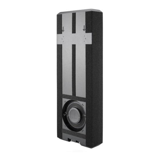
THE ENCLOSURE The Fathom ICS enclosure utilizes extensive architectural features Spacers and aimed at improving rigidity while keeping a very low profile and minimal padding will vary to ensure a proper fit. wall thickness. A unique port design vents through a slot located at the perimeter of the driver mount to enhance efficiency and low-bass output. - Page 6 THE SUBWOOFER Derived from JL Audio’s groundbreaking technologies used to develop our free-standing powered subwoofers, the 8-inch Fathom® ICS subwoofer systems deliver remarkable bass performance, while remaining largely concealed within most home audio/theater environments. The 8-inch diameter driver is smaller and easily integrates into most ceiling and wall cavities, operating through very small grilles.
- Page 7 THE AMPLIFIER Engineered with powerful features and versatile functionality, the Fathom SA-600W is a state-of-the-art amplifier designed to power a top-flight subwoofer system in home theater and home audio systems. Utilizing a precisely-engineered switching power supply, the SA-600W is capable of efficiently generating unclipped output voltages equivalent to 600 watts of RMS power, while remaining calm and stable.
-
Page 8: Tools For Installation / Prepping The Work Area
TOOLS FOR INSTALLATION Below is a list of recommended tools to perform the installation of the Fathom ICS enclosure. Depending on the specifics of your installation, you may need additional tools, hardware and/or accessories. We also recommend having a second person to assist with lifting the enclosure during in-ceiling installations. •... -
Page 9: What Is In The Box
SKU 152314 SKU 152315 WHAT IS IN THE BOX? SKU 152314 SKU 152315 SKU 152314 SKU 152314 SKU 152315 SKU 152314 SKU 152315 SKU 152339 RIGHT BRACKET SKU 152340 LEFT BRACKET SKU 152314 SKU 152315 SKU 152340 * Part A - Wallboard Template * Part B: Upper Stud Mount * Part C - Lower Stud Mount (x1) SKU: 152314... -
Page 10: Enclosure Mounting Hardware
ENCLOSURE MOUNTING HARDWARE The table at right lists the correct enclosure mounts to use by Ceiling/Wall Type Mount Part Note application type (see page 10). Before Cavity Width proceeding, identify and familiarize Upper Stud Mount Part B yourself with the appropriate mounts Pre-Attached Joist Width Lower Stud Mount... -
Page 11: Enclosure Installation Procedure
ENCLOSURE MOUNTING APPLICATIONS The Fathom ICS enclosure package includes all parts and hardware necessary for the installation of one (1) enclosure. Since a portion of the enclosure will be inaccessible after installation, we strongly recommend reading these instructions completely before beginning the installation process. - Page 12 IN-CEILING INSTALLATION Evaluating the Ceiling Cavity The ICS enclosure is designed to mount in between two joists, within a ceiling cavity, so anything coming into contact with it can lead to unwanted vibrations and rattles that cannot be accessed/ 5.50-inches corrected after the installation.
- Page 13 Remove the Floor Support (Part D) To simplify installation, the enclosure is shipped with the following parts pre-attached: Part A – Wallboard Template Part B – Upper Stud Mount Part C – Lower Stud Mount Part D – Floor Support (shrink wrapped to enclosure) For in-ceiling installations, the Floor Support (Part D) will not...
- Page 14 IN-CEILING INSTALLATION Type: IC-1 Mounting Hardware Joist Width Range Mount Part Note The table at right lists the Upper Stud Mount Part B correct enclosure mounts to use Pre-Attached Lower Stud Mount Part C for installation into ceiling cavities ½ 16-inches to 17 -inches with joist widths ranging 16-inches...
- Page 15 IN-CEILING INSTALLATION Type: IC-1 Test Fit Enclosure With the assistance of a helper, lift the enclosure into the ceiling cavity, positioning the Stud Mounts (Parts B & C) above the ends of the Joist Mounting Brackets (Parts E & F) and slide the enclosure inward until the Stud Mounts (Parts B &...
- Page 16 IN-CEILING INSTALLATION Type: IC-1 Mounting the Enclosure Place an L-Bracket (Part J) at one of the corner ends of the enclosure, with its slotted openings positioned over the pilot holes. Within each slotted opening, select two non-adjacent pilot holes (spaced one to two holes apart) and fully install two #8 x 1.00-inch pan head screws.
- Page 17 This page intentionally left blank. | Fathom ICS Page 17...
-
Page 18: In-Ceiling Installation Type
IN-CEILING INSTALLATION Type: IC-2 Mounting Hardware Joist Width Range Mount Part Note The table at right lists the correct Left Joist Mounting Brackets (x2) Part E enclosure mounts to use for installation Right Joist Mounting Brackets (x2) Part F into ceiling cavities with joist widths Extended Upper Stud Mount Part G Replaces... - Page 19 IN-CEILING INSTALLATION Type: IC-2 Understanding the Extended Stud Mounts The Extended Stud Mounts (Parts G & H) are designed so the enclosure can be positioned at the center of the ceiling cavity or towards a joist, away from the wide end of the Extended Stud Mounts (Parts G &...
-
Page 20: Figure 11
IN-CEILING INSTALLATION Type: IC-2 Attach the Extended Stud Mounts The pre-attached Stud Mounts (Parts B & C) will not be used in this application. Place the enclosure on a supported surface/table and remove the Stud Mounts (Parts B & C) for recycling (retain the #8 x 1.25-inch wafer head screws). - Page 21 IN-CEILING INSTALLATION Type: IC-2 Test Fit Enclosure With the assistance of a helper, lift the enclosure into the ceiling cavity, positioning the Extended Stud Mounts (Parts G & H) above the ends of the Joist Mounting Brackets (Parts E & F) and slide the enclosure inward until the Extended Stud Mounts (Parts G &...
- Page 22 IN-CEILING INSTALLATION Type: IC-2 Understanding the L-Bracket Extensions Designed to attach to the top and bottom ends of the enclosure, the L-Bracket Extensions (Part I) permit the enclosure to be installed in ceiling cavities with joist widths ranging from greater than 17 ½-inches to 25 ½-inches on center.
- Page 23 IN-CEILING INSTALLATION Type: IC-2 Understanding the L-Bracket Extensions continued... The L-Bracket Extensions (Part I) and L-Brackets (Part J) are attached to the enclosure using #8 pan head screws. Refer to the info listed below for specific screw quantity and length criteria.
- Page 24 IN-CEILING INSTALLATION Type: IC-2 Mounting the Enclosure Referring to the info on pages 22 and 23, position one L-Bracket Extension (Part I) at each end of the enclosure, centered between the ceiling joists, with its pre-drilled pilot holes aligned with the pilot holes in the enclosure.
-
Page 25: Enclosure. Next, Fully Tighten All Screws
IN-CEILING INSTALLATION Type: IC-2 Mounting the Enclosure cont’d... Place an L-Bracket (Part J) at one of the corner ends of the enclosure, with its slotted openings positioned over the pilot holes. Select two, non-adjacent pilot holes within each slotted opening (one to two holes apart) and fully install two #8 x 1.00-inch pan head screws. - Page 26 IN-WALL INSTALLATION Type: IW-1 Evaluating the Wall Cavity The ICS enclosure can be mounted 5.50-inches in between two studs, within a wall minimum cavity, constructed from 2 x 6 studs or larger. Once installed, anything coming into contact with it can lead to unwanted vibrations and rattles that cannot be accessed/corrected after the installation.
- Page 27 IN-WALL INSTALLATION Type: IW-1 Attach the Floor Support (Part D) To simplify installation, the enclosure is shipped with the following parts pre-attached: Part A – Wallboard Template Part B – Upper Stud Mount Part C – Lower Stud Mount Part D – Floor Support (shrink wrapped to enclosure) Place the enclosure on a supported surface/table and remove the shrink...
- Page 28 IN-WALL INSTALLATION Type: IW-1 Set the Enclosure Position Place the enclosure into the wall cavity, with both Stud Mounts (Parts B & C) pressed against the stud faces and supported by the Floor Support (Part D). Using a level and the ends of the Stud Mounts (Parts B &...
- Page 29 IN-WALL INSTALLATION Type: IW-1 Mounting the Enclosure Place an L-Bracket (Part J) at one of the corner ends of the enclosure, with its slotted openings positioned over the pilot holes. Select two, non-adjacent pilot holes within each slotted opening (one to two holes apart) and fully install two #8 x 1.00-inch pan head screws.
- Page 30 ROUTING THE SPEAKER CABLE Route speaker cable to the push terminals located at the bottom of the enclosure and remove the outer jacketing to expose the individual wires. Two rubber covers are included to insulate the speaker terminals. Feed the individual wires through each rubber cover and remove the wire insulation.
- Page 31 FOAM GASKET INSTALLATION The included energy absorbing adhesive foam gasket strip is used to reduce the potential for noise and vibration between the joists/studs and wallboard. Remove the backing and firmly press the foam gasket strip to all joist/ stud faces surrounding the enclosure. Use a utility knife or scissors to cut and trim the edges of the foam gasket strip.
-
Page 32: Grille Installation Procedure
GRILLE INSTALLATION PROCEDURE Before you Begin The following instructions assume the ICS Enclosure has already been installed. The Grille Assembly The grille assembly is comprised of a removable outer metal mesh and grille tray. The grille assembly should be installed only after the surrounding wallboard and grille assembly have been painted and the room’s interior is free of construction debris. -
Page 33: Figure 2
Grille Assembly Installation With the Wallboard Template (Part A) removed, test fit the grille tray by inserting it into the opening with the JL Audio logo positioned at the bottom of the enclosure. The grille (Figure 2) tray’s outer edge should make contact with the outer wallboard surface. - Page 34 Notes Page 34 | Fathom ICS...
- Page 35 Notes | Fathom ICS Page 35...
-
Page 36: Specifications
8-inch Fathom® ICS Enclosure Specifications: Specifications Fathom® ICS-SYS-108 Fathom® ICS-SYS-208 Enclosure Type: Single Ported Enclosure Two Ported Enclosures 8-in. 8-in. Driver(s): (nominal diameter) (nominal diameter) in each of two enclosures 24.9 Hz - 109 Hz (+/- 1.5 dB) Frequency Response (anechoic): -3dB at 24.6 Hz / 111 Hz -10dB at 23.4 Hz / 118 Hz 31.62 sq.
Need help?
Do you have a question about the FATHOM ICS-SYS-108 and is the answer not in the manual?
Questions and answers