Table of Contents
Advertisement
Quick Links
Advertisement
Table of Contents

Related Manuals for Siborg LCR-Reader MPA

Summary of Contents for Siborg LCR-Reader MPA
-
Page 2: Table Of Contents
Voltage Mode 7.4.1 Controls Transient Voltage Waveforms (Oscilloscope Mode) 17 7.5.1 Oscilloscope mode settings Frequency Meter Mode 7.6.1 Changing the sub-mode 7.6.2 Frequency, Period control Signal Generator Mode 7.7.1 Controls System Menu Entries 7.8.1 Power © Copyright Siborg Systems Inc. -
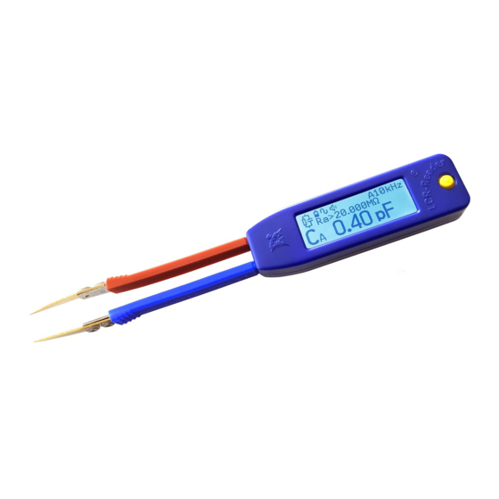
Page 3: Device Use
• Automatic adjustment of test signal to 0.1 V peak-to-peak for in-circuit measurements • Designated ESR measurements • Easy Open/Short calibration for better measurement accuracy • Automatic detection of diode polarity and short circuit • AC/DC voltage measurements • Frequency meter © Copyright Siborg Systems Inc. -
Page 4: What Is Included In The Package
100 Ω resistor is applied to the DUT connected at points A and B. The amplitude and frequency of the Test Signal V are adjustable. It is also possible to apply © Copyright Siborg Systems Inc. -
Page 5: Calculation Of Parameters
Inductance L = Xs/(2πf). Q = |Xs|/Rs. D = 1/Q. |Z| = In automatic mode the device automatically selects the optimum frequency and the equivalent circuit for measurements. Users can also manually select measurement mode and frequency of © Copyright Siborg Systems Inc. -
Page 6: Safety Measures And General Instructions
Never measure Charged Capacitors Do not make measurements while the device is charging Charge the battery using a USB port of a computer or a DC charger 5 V +/- 5%. Do not use damaged cables or chargers. © Copyright Siborg Systems Inc. -
Page 7: Device Controls
1. If you rotate and hold the device the screen will flip orientation to the hand being used. * 2. If you place the device on a flat surface with the screen facing up, after a few seconds the device will go into © Copyright Siborg Systems Inc. -
Page 8: Charging The Battery
To set the default operating mode (R-L-C-D, RDC+LED, Voltage, etc.), press and hold the joystick for two beeps. This mode is then stored in the device memory and will be activated when the device is powered on next time. © Copyright Siborg Systems Inc. -
Page 9: Modes Of Operation
To select the mode, select R-L-C-D in the main menu. In order to get access to the mode parameters (hidden sub-menu) push the joystick to the right for one beep. A typical screen for R-L-C-D mode looks as follows: © Copyright Siborg Systems Inc. -
Page 10: Measurements
R-L-C- D parameter sub-menu by pushing the joystick to the right for one beep to activate the hidden sub-menu. In this case both the © Copyright Siborg Systems Inc. -
Page 11: Quick Controls
To eliminate the offset, push the joystick to the right, hold for 2 beeps and release. When measuring small capacitances less than 100 pF, use LCR-Reader Offset Calibration Board included in the package for the open calibration. Insert the test leads at the © Copyright Siborg Systems Inc. -
Page 12: Capacitance Offset Calibration Board
The menu tree is shown in detail in the following diagram: 7.2.1 Primary Parameter In Auto mode the type of measured component is determined automatically: R: Resistor, L: Inductance, C: Capacitor, D: Diode. © Copyright Siborg Systems Inc. -
Page 13: Secondary Parameter
For Capacitance measurements in Automatic equivalent circuit regime and Auto signal level Serial circuit is used for impedance values lower that 100 Ohms. If signal level is not in the Auto regime, serial equivalent circuit is © Copyright Siborg Systems Inc. -
Page 14: Sound
• C-voltage is Off • Data Hold is Off If you hold the joystick up to 2 beeps, then all parameters are stored in the non-volatile memory and will be loaded when the device is powered on. © Copyright Siborg Systems Inc. -
Page 15: Large Cap
1.0 Vrms and 0.1 Vrms 7.2.13 Super Large Cap > 40 mF Measurement • Push Joystick right for 2 beeps to make calibration eliminating the offset. Only short calibration is required. • Push Joystick to the left to © Copyright Siborg Systems Inc. -
Page 16: Rdc+Led Mode
7.3.3 R test at 1.3 V and R test at 100mV To select the R-test Mode push the joystick up, resistor symbol will be displayed in the top left corner. If you push up again, the © Copyright Siborg Systems Inc. -
Page 17: Voltage Mode
• Push the joystick to the left for 1 beep to turn on and off the capture mode of the maximum and minimum voltage values. In this mode the device continuously records and displays minimum and maximum values of the voltage/current as well as the instant value. © Copyright Siborg Systems Inc. -
Page 18: Transient Voltage Waveforms (Oscilloscope Mode)
Push the joystick to the right for 1 beep to return to the Frequency main menu. Push the joystick to the right for 1 beep to return to the Frequency © Copyright Siborg Systems Inc. -
Page 19: Signal Generator Mode
Turn-off Time: Push joystick Up/Down to Increase/Decrease Turn-Off Time Flip Turn-off: Off/On/Exit Power Save Mode: Off/On/Exit Exit 7.8.2 Sound Loud/Moderate/Quiet/Exit 7.8.3 Display Hand: Right/Left/Auto/Exit Brightness: Push joystick Up/Down to Increase/Decrease Brightness Backlight: Push joystick Up/Down to Increase/Decrease Backlight Exit © Copyright Siborg Systems Inc. -
Page 20: Serial Number
Customers can contact customer support by phone +1-519-888- 9906 or by e-mail support@LCR-Reader.com. When contacting technical support, please provide the following information: • Model number • Software version number • Serial number of the device • Purchase Receipt © Copyright Siborg Systems Inc. -
Page 21: Maintenance
This warranty does not cover LCD damage, physical damage to the Joystick; electrical damage of the product due to high voltage / charged capacitor or improper battery type. The design and © Copyright Siborg Systems Inc. -
Page 22: Specifications
Loss Angle (θ) -90 to 90° LED/Diode Maximum Voltage Test 3.2 V Voltage Measurement Accuracy ±(3%+5) V Maximum Test Current 16 mA Current Measurement Accuracy ±(3%+5) А Voltage Range - 15 V to 15 V © Copyright Siborg Systems Inc. -
Page 23: Fcc Compliance
Series Series, 10кΩ 0.001кΩ 0.1%+3 0.1%+3 0.1%+3 0.2%+3 Parallel 100кΩ 0.01 кΩ 0.1%+3 0.1%+3 0.1%+3 0.5%+3 Parallel 1MΩ 0.1кΩ 0.2%+3 0.2%+3 0.2%+3 1%+3 Parallel 10MΩ 0.001MΩ 1%+5 0.5%+5 1%+5 Parallel 20MΩ 0.01MΩ 3%+5 3%+5 Parallel © Copyright Siborg Systems Inc. -
Page 24: Dc Resistance
Resolution 0.5Vrms 0.1Vrms 10pF 0.001pF 5%+200 100pF 0.01pF 3%+100 5%+200 1000pF 0.1pF 1%+10 3%+20 10nF 0.001nF 0.5%+3 2%+5 100nF 0.01nF 0.5%+3 2%+3 1000nF 0.1nF 0.5%+3 2%+3 10μF 0.001μF 1%+3 2%+3 100 μF 0.01μF 1%+3 2%+3 © Copyright Siborg Systems Inc. -
Page 25: Dc Capacitance Measurement
• Presence of the AC will result in lower accuracy 13.4.8 AC Voltage Range Resolution Accuracy Frequency 0.1 -15 V 0.01 V 5%+3 30 - 3000 Hz • Presence of the DC offset will result in lower accuracy © Copyright Siborg Systems Inc. -
Page 26: Low Frequency Dds Signal Generator
0.09 2200 0.16 0.14 0.12 0.10 0.09 0.08 3300 0.11 0.10 0.09 0.07 0.08 0.06 4700 0.09 0.08 0.07 0.06 0.06 0.05 6800 0.06 0.05 0.05 0.05 8200 0.06 0.05 0.04 10000 0.05 0.04 0.04 © Copyright Siborg Systems Inc. -
Page 27: Supplement B
0.074 1000 0.066 0.063 0.060 0.057 0.054 0.048 2200 0.038 0.036 0.034 0.032 0.031 0.027 3300 0.032 0.030 0.029 0.027 0.026 4700 0.027 0.025 0.024 0.023 6800 0.024 0.023 0.022 10000 0.021 0.020 15000 0.020 © Copyright Siborg Systems Inc. - Page 28 LCR-Reader-MPA Auto R - Resistance C - Capacitance L - Inductance Primary Parameter Z - Impedance Calibrate Large Cap Toggle Large/Super Test Signal Auto R - Resistance Secondary R-L-C-D Parameter Q- Quality Push to Open D - Loss Tangent Main Hidden Menu Test Frequency...
Need help?
Do you have a question about the LCR-Reader MPA and is the answer not in the manual?
Questions and answers