Table of Contents
Advertisement
Quick Links
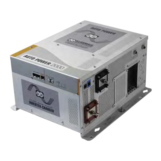
Auto Power 2000W & 3000W Inverter/Chargers
Model Numbers:
091-269-12-2000
091-269-12-3000
File: 091-269-12-XXXX
Rev: A.
Revised By:PSS/JRN
Date: 07-30-2019
170 Cherry Avenue
West Sayville, NY 11796
www.kussmaul.com
2 YEAR WARRANTY
K
Auto Power 2000W shown.
Installation Guide
Ph: 800-346-0857
Fax: 631-567-5826
sales@kussmaul.com
Advertisement
Table of Contents


Need help?
Do you have a question about the Auto Power 2000 and is the answer not in the manual?
Questions and answers