Table of Contents
Advertisement
Quick Links
INSTALLATION AND
OPERATION MANUAL
"CUCIMIX"
ROUND BRATT PANS WITH MIXER, GAS TYPE
MODD. UCBTG018_V1
FOR YOUR SAFETY:
Do not store or use gasoline or any other flammable liquids and
vapours in the vicinity of this or any other appliance.
WARNING:
Improper installation, operation, adjustment, alteration, service or
maintenance can cause property damage, injury or death.
Read the installation, operating and maintenance instructions
thoroughly before installing, operating or servicing this equipment.
PURCHASER: Instructions to be followed in the event that the operator
of this appliance smells gas must be posted in a prominent location.
This information shall be obtained by consulting the local gas supplier.
Advertisement
Table of Contents

Related Manuals for Firex CUCIMIX UCBTG018 V1


Summary of Contents for Firex CUCIMIX UCBTG018 V1
- Page 1 INSTALLATION AND OPERATION MANUAL “CUCIMIX” ROUND BRATT PANS WITH MIXER, GAS TYPE MODD. UCBTG018_V1 FOR YOUR SAFETY: Do not store or use gasoline or any other flammable liquids and vapours in the vicinity of this or any other appliance. WARNING: Improper installation, operation, adjustment, alteration, service or maintenance can cause property damage, injury or death.
- Page 2 MODEL : ______________________________________________________ NR. SERIAL : ______________________________________________________ The model and serial number are indicated on the rating plate Firex srl, Z.I.Gresal, 28 32036 Sedico BELLUNO ITALIA TELEPHONE: (0039) 852700 ; FAX: (0039) 852858 The manual is available upon request to: service@firex.it...
-
Page 3: Table Of Contents
INTRODUCTION 04-UCBTG018_V1-DIMU-00-EN TABLE OF CONTENTS 1 INTRODUCTION............................ 6 SYMBOLS AND PICTORIALS ........................6 GENERAL REMINDERS ........................... 6 IMPORTANT NOTES FOR INSTALLATION ..................... 7 2 SAFETY ..............................8 OVERVIEW ............................... 8 WARNINGS ............................... 9 TABLE OF PAN PRODUCT LEVELS ...................... 12 3 DESCRIPTION OF THE MACHINE ..................... - Page 4 04-UCBTG018_V1-DIMU-00-EN INTRODUCTION 9 USING THE MACHINE ........................29 10 TOUCH SCREEN ..........................29 11 MAIN MENU ............................30 12 SETTINGS MENU ..........................31 13 PROGRAMS MENU ..........................32 14 COOKING LAYOUT ..........................33 14.1 STATUS BAR ............................34 14.2 COOKING AREA ............................. 35 14.2.1 COOKING ICONS (MEANING) ..........................
- Page 5 INTRODUCTION 04-UCBTG018_V1-DIMU-00-EN 23 MOVING THE PAN ..........................64 24 CLEANING AND CARE ........................66 24.1 GENERAL INFORMATION ........................66 24.2 DAILY CLEANING ........................... 66 24.3 MIXER CLEANING ..........................67 24.4 ASSEMBLY AND DISASSEMBLY VERTICAL SCRAPER FROM THE MIXER ........70 24.5 PRECAUTIONS IN CASE OF PROLONGED INACTIVITY ..............
-
Page 6: Introduction
04-UCBTG018_V1-DIMU-00-EN INTRODUCTION INTRODUCTION SYMBOLS AND PICTORIALS ATTENTION! This indicates a dangerous operation or situation. ATTENTION! This indicates a regulation or an obligation. ATTENTION! This indicates the prohibition to carry out an operation. NOTE! This indicates a recommendation or information deemed to be particularly important. GENERAL REMINDERS The business units manager, where the unit will be installed, have an obligation, in accordance with the regulations, read carefully the contents of this manual and teach... -
Page 7: Important Notes For Installation
INTRODUCTION 04-UCBTG018_V1-DIMU-00-EN IMPORTANT NOTES FOR INSTALLATION The following points are to insure the safe installation and operation of this equipment: Before connecting any parts of the appliance to supplies, make sure that the latter is equivalent the requirements stated in the rating plate, if the appliance has been designed for these supplies. -
Page 8: Safety
04-UCBTG018_V1-DIMU-00-EN SAFETY SAFETY OVERVIEW Read the warnings contained in this manual carefully as they provide important information regarding safe installation, maintenance and use. These appliances should only be used by personnel trained to use them. The appliance must be operated under close supervision. ... -
Page 9: Warnings
SAFETY 04-UCBTG018_V1-DIMU-00-EN WARNINGS All installation and maintenance work must only be carried out by a company belonging to the relevant industry register. Fire protection regulations must be strictly adhered to. The machine should be serviced at least once a year to ensure it is in prime condition. - Page 10 04-UCBTG018_V1-DIMU-00-EN SAFETY Wear rubber gloves, goggles or a face shield and protective clothing when using the appliance. Risk of scalding! The machine controls can only be hand operated. Damage caused by the use of pointed, sharp and similar objects shall void any warranty claims. It is essential to wash the inside of the cooking pan thoroughly before setting up the appliance for first use.
- Page 11 SAFETY 04-UCBTG018_V1-DIMU-00-EN If the power cord is damaged, it must be replaced by the manufacturer or by a servicing company or a similarly qualified person in order to avoid hazards. When an appliance is supplied on casters (optional), there is a restraint on the appliance and, if disconnected of the restraint is necessary, to reconnect this restraint after the appliance has been returned to its original position.
-
Page 12: Table Of Pan Product Levels
04-UCBTG018_V1-DIMU-00-EN SAFETY TABLE OF PAN PRODUCT LEVELS ATTENTION: The cooking pan must be filled respecting the minimum and maximum values (including the food to be cooked) indicated in the table depending on the cooking method. ATTENTION: Failure to comply with this requirement may cause serious injury to persons and compromise the operation of the appliance Cooking method PAN LEVELS TO BE RESPECTED... -
Page 13: Description Of The Machine
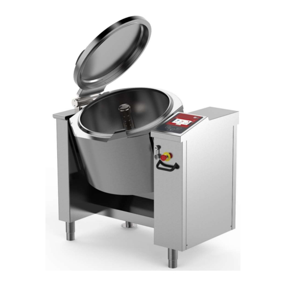
DESCRIPTION OF THE MACHINE 04-UCBTG018_V1-DIMU-00-EN DESCRIPTION OF THE MACHINE DESCRIPTION Round Bratt pans with built-in mixer, ideal for cooking meat, sauces, risotto, fillings and for all those dishes that require the ingredients to be worked gently. Uniform cooking and a high-quality end product are the result of cutting edge and simple to use technology. The appliance can only be used for cooking food in industrial kitchens. -
Page 14: Operating Parts
04-UCBTG018_V1-DIMU-00-EN DESCRIPTION OF THE MACHINE OPERATING PARTS 01 Rating plate 06 Lid 02 Cooking pan 07 Sensor in the pan 03 Control panel 08 Mixer 04 Emergency button 09 Mixer locking ring 05 Plug USB... -
Page 15: Technical Data
TECHNICAL DATA 04-UCBTG018_V1-DIMU-00-EN TECHNICAL DATA TECHNICAL DATA UCBTG018_V1 UCBTG018_V1 TECHNICAL DATA (DIMEMSIONS) Equipment dim.A Inches 42.52 Equipment dim.B Inches 32.68 Equipment dim.H1 Inches 42.53 Equipment dim.H Inches 37.21 Equipment dim.H2 Inches 67.92 Tank drain height H3 Inches 14.57 TECHNICAL DATA (FUNCTIONALITY) Kettle diameter Inches 23.62... -
Page 16: Plant Connection Ubtg018_V1
04-UCBTG018_V1-DIMU-00-EN TECHNICAL DATA PLANT CONNECTION UBTG018_V1 LEGEND: Electrical connection (Conduit 1/2”) Optional Gas connection Hot water connection BACK See “CLEARANCE REQUIREMENTS” Cold water connection... -
Page 17: Gas Inlet Pressures
TECHNICAL DATA 04-UCBTG018_V1-DIMU-00-EN GAS INLET PRESSURES GAS REQUIREMENT TABLE Type of gas Natural Propane Operating gas pressure in W.C. (mbar) 7.0 (17.4) 11.0 (27.4) Min.Supply gas pressure in W.C. (mbar) 6.0 (14.9) 9.0 (22.4) Max.Supply gas pressure in W.C. (mbar) 10.5 (26.1) 13.0 (32.3) Warning: if the supply pressure is lower than “... - Page 18 04-UCBTG018_V1-DIMU-00-EN TECHNICAL DATA FIG. MAIN BURNER – PRIMARY AIR REGULATION LEGEND: Burner Air regulation square Injector (tab."GAS DATA") Square lock screws Injector pipe See tab."GAS DATA" ...
- Page 19 TECHNICAL DATA 04-UCBTG018_V1-DIMU-00-EN FIG. GAS CONTROL VALVE (822) LEGEND: Coil 6,1 Ω (EV1) Outlet pressure intake (manifold pressure) Coil 39,1 Ω (EV2) Pressure regulator Inlet pressure intake (supply pressure)
-
Page 20: Transport, Storage, Unpacking
04-UCBTG018_V1-DIMU-00-EN TRANSPORT, STORAGE, UNPACKING TRANSPORT, STORAGE, UNPACKING TRANSPORT The movement of the machine must be performed by a qualified operator for use of lifting and transport equipment in accordance with the laws of the country of the user of the machine. The machine can be transported with a normal means (forklift or transpallet)capable of supporting its weight and size (see.tab. -
Page 21: Storage
TRANSPORT, STORAGE, UNPACKING 04-UCBTG018_V1-DIMU-00-EN STORAGE Store the appliance in a closed environment protected against atmospheric agents. Keep the appliance away from humidity and temperature ranges Protect the appliance from shocks and stresses Ensure that the appliance is in contact with corrosive substances RECEIPT AND UNPACKING Upon receipt of the machine check that the packaging is undamaged. -
Page 22: Installation
04-UCBTG018_V1-DIMU-00-EN INSTALLATION INSTALLATION INSTALLATION CODES AND STANDARDS Installation must conform with local codes, or in the absence of local codes, with the National Fuel Gas Code, ANSI Z223.1/NFPA 54, or the Natural Gas and Propane Installation Code, CSA B149.1, as applicable. 1. -
Page 23: Positioning
INSTALLATION 04-UCBTG018_V1-DIMU-00-EN POSITIONING CLEARANCE REQUIREMENTS This unit must be installed in accordance with the clearances shown on the rating label which is adhered to the unit. CLEARANCES Noncombustible construction Combustible construction Back 2" (50 mm) 8" (200 mm) Right Side 25"... -
Page 24: Connections
04-UCBTG018_V1-DIMU-00-EN CONNECTIONS CONNECTIONS Attention: When the appliance is equipped with casters (optional), the installation shall be made with a connector complying with either ANSI Z21.69 CSA 6.16 and a quick- disconnect device complying with ANSI Z21.41 CSA 6.9. Adequate means must be provided to limit the moviment of the appliance without depending on the connector and the quick-connector device or its associated piping to limit the appliance movement. -
Page 25: Water Connection (Optional)
CONNECTIONS 04-UCBTG018_V1-DIMU-00-EN Replace the cover and secure it with screws. Any damage caused by water/steam infiltration or insects, due to the machine panels not being closed (after installation or maintenance) shall void any warranty claims. WATER CONNECTION (optional) The equipment is to be installed with adequate backflow protection to comply with applicable federal, state, and local codes. -
Page 26: Gas Connection
04-UCBTG018_V1-DIMU-00-EN CONNECTIONS GAS CONNECTION The choice of the gas piping depends on the diameter required for the type of gas, appliance and installation and should be performed in conformity with current regulations. The rating plate on the lower right side of the unit indicates the type of gas your unit is equipped to burn. -
Page 27: Control Of The Gas Pressure
CONNECTIONS 04-UCBTG018_V1-DIMU-00-EN 7.3.1 CONTROL OF THE GAS PRESSURE Gas pressure is measured directly in the gas valve. A = GAS INLET PRESSURE INTAKE B = GAS MANIFOLD PRESSURE INTAKE ONLY FOR THE EUROPEAN MARKET The gas inlet pressure intake is on the gas feed pipe (FIG.1 "A") (See PLANT CONNECTION). Before connecting the gauge remove the screw of the inlet pressure intake (FIG.1 "B"). -
Page 28: Commissioning And Testing
04-UCBTG018_V1-DIMU-00-EN COMMISSIONING AND TESTING COMMISSIONING AND TESTING Once all the connections have been made, the appliance and the overall installation must be checked following the directions given in this manual. CHECK IN PARTICULAR: That the protective film has been removed from the external surfaces; That the panels of the machine are closed correctly;... -
Page 29: Using The Machine
USING THE MACHINE TOUCH SCREEN 1-On-off switch 2- 7" TFT resistive display 3- Keypad for movements (mixer, pan) 2- 7" TFT resistive display 1-On-off switch 3- Keypad for movements (mixer, pan) -
Page 30: Main Menu
04-UCBTG018_V1-DIMU-00-EN MAIN MENU MAIN MENU SETTINGS PROGRAMS PROGRAMS Setting manual cooking parameters Carrying out manual cooking Running cooking programs SETTINGS Appliance setting-user; creating-editing cooking programs language date-time firmware update colors EXPORT (HACCP data) Appliance setting - installer/technical assistant;... -
Page 31: Settings Menu
SETTINGS MENU 04-UCBTG018_V1-DIMU-00-EN SETTINGS MENU PROGRAMS LANGUAGES FIRMWARE DATE-HOUR EXPORT TEST I/0 PARAMETERS COLORS IMPORT PROGRAMS Creating-editing cooking programs LANGUAGES Language setting FIRMWARE Firmware update (from USB) DATE-HOUR Current Date and Time setting TEST I/0 Test I/O board (only with password) ... -
Page 32: Programs Menu
04-UCBTG018_V1-DIMU-00-EN PROGRAMS MENU PROGRAMS MENU MANUAL SAUCES MEAT FAVORITES CHEF POULTRY FISH Setting manual cooking parameters Carrying out manual cooking MANUAL Running cooking programs FAVORITES MEAT... -
Page 33: Cooking Layout
COOKING LAYOUT 04-UCBTG018_V1-DIMU-00-EN COOKING LAYOUT 01:27: 35 XXX1234 17/12/ 2016 100°C 180°C 00:45:00 20°C 20°C --:--:-- START STATUS BAR 01:27: 35 XXX1234 17/12/ 2016 ↓ COOKING AREA _________________________________________________________ 180°C 100°C 00:45:00 20°C 20°C --:--:-- _________ __________ ↑ MESSAGE COLUMN FUNCTION COLUMN ↑ FUNCTION BAR START... -
Page 34: Status Bar
04-UCBTG018_V1-DIMU-00-EN COOKING LAYOUT 14.1 STATUS BAR 01:27: 35 XXX1234 17/12/ 2016 STAND-BY/RETURN KEY; 3 sec → HOME ↓ COOKING/PROGRAM IN PROGRESS. ↓ COOKING/PROGRAM IN PROGRESS (PAUSED) AWAITING ACTION. XXX1234 Name of cooking program selected PROGRAM IN THE LIST OF FAVOURITES (not present in manual cooking) PROGRAM PHASE IN PROGRESS (not present in manual cooking) 01:27: 35 CURRENT TIME AND DATE... -
Page 35: Cooking Area
COOKING LAYOUT 04-UCBTG018_V1-DIMU-00-EN 14.2 COOKING AREA < TIME TYPE COOKING METHOD> 100°C 180°C 00:45:00 < SETPOINT SETPOINT > --:--:-- < COUNTDOWN VALUE MEASURED> 20°C 20°C HEATING IN OPERATION MINIMUM HEATING HEATING OFF AS SETPOINT REACHED OR FOR WAITING (L COLUMN ICONS) -
Page 36: Cooking Icons (Meaning)
04-UCBTG018_V1-DIMU-00-EN COOKING LAYOUT 14.2.1 COOKING ICONS (MEANING) Left or central icon: main control (when the SETPOINT is reached, heating stops and the countdown of the cooking time starts) ↓ ↑ Right icon: secondary control (when the SETPOINT is reached, the heating stops) Name Icon Description... -
Page 37: Message Column (L)
COOKING LAYOUT 04-UCBTG018_V1-DIMU-00-EN 14.3 MESSAGE COLUMN (L) INFORMATION AND REQUESTS INDICATOR L COLUMN buzzer Light Icon Description Behaviour Indicator Pan out of position (for Icon present when pan out of position cooking) Pan movement not Icon present only when you want to allowed perform a pan movement in an unauthorised phase. -
Page 38: Function Bar
04-UCBTG018_V1-DIMU-00-EN COOKING LAYOUT 14.5 FUNCTION BAR EXTRA KEY (functions) START/STOP KEY DELAYED COOKING KEY ↓ ↓ ↓ 14.5.1 START-STOP KEY FOR RUNNING PROGRAMS Attention: the START/STOP key indicates the action that will be performed by pressing the key! The machine status is indicated by the icon on the top left icon on the top left With key presence Machine status... - Page 39 COOKING LAYOUT 04-UCBTG018_V1-DIMU-00-EN To avoid accidentally stopping the cooking program in progress, press the STOP key and the following screen appears: If the STOP key has been pressed incorrectly, wait approximately 5 seconds and you return to the program in progress. If instead you want to stop the program, slide the coloured square from the triangle to the square and release the key.
-
Page 40: Extra Key
04-UCBTG018_V1-DIMU-00-EN COOKING LAYOUT 14.5.2 EXTRA KEY Pressing the key it is possible to access the following functions: H2O loading into the vessel, vessel tilting and motorized vessel discharge (optional) PAN MOVEMENT ↓ 14.5.3 COOKING WITH DELAY TIMER KEY Press the key to access the settings for cooking with delay timer. -
Page 41: Cooking Methods In Detail
COOKING METHODS IN DETAIL 04-UCBTG018_V1-DIMU-00-EN COOKING METHODS IN DETAIL 15.1 COOKING Icon Description For braising that requires a temperature up to 220°C; the temperature regulation is controlled by the sensor (PT1000) located on the bottom of the pan For gentle cooking; the temperature regulation is controlled by the sensor (PT1000) located inside the pan, in contact with the product, and by the sensor located on the bottom of the pan. -
Page 42: Setting Setpoint Parameters
04-UCBTG018_V1-DIMU-00-EN SETTING SETPOINT PARAMETERS SETTING SETPOINT PARAMETERS 16.1 SETTING SETPOINT VALUES WITH THE KEYPAD The following screen appears when setting any setpoint value: left column: parameter of which you are changing the setpoint value. right column: keypad + cursor for changing the setpoint. ------------------- 100°C 20°C... - Page 43 SETTING SETPOINT PARAMETERS 04-UCBTG018_V1-DIMU-00-EN The values in the right column will be changed as follows: SETTING WITH KEYPAD TYPE THE DESIRED VALUE. ATTENTION : THE VALUE MUST BE BETWEEN min AND max! SETTING WITH CURSOR QUICK SETTING PRECISE SETTING ------------------ ------------------ ←...
-
Page 44: Cooking Parameters Setting
04-UCBTG018_V1-DIMU-00-EN COOKING PARAMETERS SETTING COOKING PARAMETERS SETTING The setting of the following parameters can only be made from the menu: 1. PROGRAMS + MANUAL 2. SETTINGS + PROGRAMS 17.1 SETTING COOKING METHOD AND TEMPERATURE 180°C 00:45:00 100°C 20°C --:--:-- 20°C AREA HIGHLIGHTED = SELECTION/SETTINGS SETTING COOKING METHOD SELECTING COOKING METHOD (see Cooking... -
Page 45: Setting Cooking Time
COOKING PARAMETERS SETTING 04-UCBTG018_V1-DIMU-00-EN 17.2 SETTING COOKING TIME SELECTING COOKING TIME < COOKING TIME SETPOINT (see SETPOINT) 00:45:00 < COOKING TIME COUNTDOWN --:--:-- SELECTING COOKING TIME Cooking time Cooking time Infinite time (at setpoint °C) (immediate) → → → ATTENTION: WHEN SELECTING THE INFINITE TIME, PRESS THE KEY INDICATED BELOW TO TERMINATE THE PROGRAM IN PROGRESS. - Page 46 04-UCBTG018_V1-DIMU-00-EN COOKING PARAMETERS SETTING SETTING COOKING TIME SETPOINT Only with 00:45:00 ↓ --------------- 00:45:00 HH:MM:SS HH: 99 max; MM: 59 max; SS: 59 max...
-
Page 47: Creating Programs (Multi-Phase)
CREATING PROGRAMS (MULTI-PHASE) 04-UCBTG018_V1-DIMU-00-EN CREATING PROGRAMS (MULTI-PHASE) FROM SETTINGS> PROGRAMS> NEW 01:27: 35 NEW PROGRAM 17/12/ 2016 180°C 00:45:00 100°C 20°C --:--:-- 20°C A PROGRAM CAN CONSIST OF 20 PHASES. THE PARAMETERS ARE CONSTANT WITHIN EACH PHASE. IF A SINGLE VALUE CHANGES, YOU NEED TO CREATE A NEW PHASE! THE CREATION OF THE PHASE CONSISTS OF ENTERING THE COOKING METHOD, COOKING TIMES, MIXER FUNCTIONS AND WALL HEATING. - Page 48 04-UCBTG018_V1-DIMU-00-EN CREATING PROGRAMS (MULTI-PHASE) > SHOWS THE CURRENT PHASE RETURNS TO PHASE 1 SETTINGS ENTERS A NEW PHASE AFTER THE HIGHLIGHTED PHASE (e.g. if the program consists of 2 phases and I want to insert a phase between 1 and 2, I have to select phase 1 and press the + key, phase 2 becomes 3 and you need to set the parameters for phase 2).
-
Page 49: Message Settings
CREATING PROGRAMS (MULTI-PHASE) 04-UCBTG018_V1-DIMU-00-EN 18.2 MESSAGE SETTINGS The following screen appears when selecting the message icon: 01:27:35 NEW PROGRAM 17/12/2016 ______ _______ ↑ ↑ ↑ MESSAGE SELECTION KEYS MESSAGE SETTINGS KEYS MESSAGE WRITING AREA MESSAGE SELECTION KEYS Icon Description MESSAGE AT THE BEGINNING OF THE PHASE MESSAGE ON REACHING SETPOINT MESSAGE AT THE END OF THE PHASE... - Page 50 04-UCBTG018_V1-DIMU-00-EN CREATING PROGRAMS (MULTI-PHASE) MESSAGE SETTINGS KEYS THE KEY ON THE TOP RIGHT TAKES ON THE FOLLOWING FUNCTIONS SPECIFIED IN RELATION TO THE SELECTED MESSAGE (START; SET °C: END) START MESSAGE Behaviour when program running No message appears The message appears ...
- Page 51 CREATING PROGRAMS (MULTI-PHASE) 04-UCBTG018_V1-DIMU-00-EN ATTENTION : IF THE MESSAGE IS SET TO OFF, ALL THE SETTINGS DESCRIBED BELOW (FLASHING, BUZZER, AND TEXT) WILL NOT APPEAR WHEN THE PROGRAM IS RUNNING! THE FOLLOWING KEYS HAVE THE SAME FUNCTIONS FOR ALL MESSAGES (START; SET °C; END) Flashing (optional) Right key...
- Page 52 04-UCBTG018_V1-DIMU-00-EN CREATING PROGRAMS (MULTI-PHASE) ENTERING MESSAGE TEXT 01:27: 35 NEW PROGRAM 17/12/ 2016 USE THE KEYPAD TO ENTER A DESCRIPTIVE TEXT (MAX 200 CHARACTERS) AND CONFIRM WITH THE KEY AFTER HAVING SET ALL THE VARIABLES WITHIN THE MESSAGE, THE RELATED MESSAGE ICON WILL SHOW WITHIN ALL THE SYMBOLS THAT SUMMARISE THE SETTINGS OF THE MESSAGE ITSELF.
-
Page 53: Saving A Program
CREATING PROGRAMS (MULTI-PHASE) 04-UCBTG018_V1-DIMU-00-EN 18.3 SAVING A PROGRAM IF YOU WANT TO ADD THE PROGRAM TO THE LIST OF FAVOURITES, PRESS THE "STAR" SYMBOL. 01:27: 35 NEW PROGRAM 17/12/ 2016 Program NOT added to favourites Program added to favourites PRESS THE "SAVE"... -
Page 54: Edit/ Copy/ Rename Program
04-UCBTG018_V1-DIMU-00-EN CREATING PROGRAMS (MULTI-PHASE) ENTER THE PROGRAM NAME AND CONFIRM WITH THE KEY ATTENTION : THE PROGRAM DOES NOT PERFORM A CHECK TO SEE IF A PROGRAM WITH THE SAME NAME ALREADY EXISTS. 2 PROGRAMS WILL BE SAVED WITH THE SAME NAME, WITH HE POSSIBILITY OF RENAMING THEM. -
Page 55: Deleting A Program
RUNNING A PROGRAM/MANUAL COOKING 04-UCBTG018_V1-DIMU-00-EN 18.5 DELETING A PROGRAM FROM SETTINGS> PROGRAMS SELECT THE CATEGORY OF THE PROGRAM OR ALL SELECT THE PROGRAM YOU WANT TO DELETE BY PRESSING ON THE NAME OF THE PROGRAM FOR ABOUT 2 SEC. ... -
Page 56: End Of Cooking
04-UCBTG018_V1-DIMU-00-EN RUNNING A PROGRAM/MANUAL COOKING THE SCREEN BECOMES 01:27: 35 MANUAL 17/12/ 2016 100°C 180°C 00:45:00 --:--:-- 20°C 20°C A SYMBOL APPEARS ON THE SIDE OF THE VALUE READ WITH THE FOLLOWING MEANINGS: HEATING IN OPERATION MINIMUM HEATING ... -
Page 57: Running Programs (Multi-Phase)
RUNNING PROGRAMS (MULTI-PHASE) 04-UCBTG018_V1-DIMU-00-EN RUNNING PROGRAMS (MULTI-PHASE) 20.1 RUNNING PROGRAMS (MULTI-PHASE) FROM PROGRAMS> SELECT THE PROGRAM THAT YOU WANT TO RUN FROM THE FOLDER: ALL; CATEGORY (MEAT, SAUCES, ETC) OR FAVOURITES PRESS THE START KEY NOTE 1) WHEN RUNNING THE PROGRAM YOU CAN CHANGE THE TEMPERATURE AND TIME SETPOINT (ONLY IN THE PHASE IN WHICH THE PROGRAM IS CURRENTLY RUNNING) BY PRESSING IN THE FIELD CORRESPONDING TO THE SET VALUES FOR ABOUT 2 sec. - Page 58 04-UCBTG018_V1-DIMU-00-EN RUNNING PROGRAMS (MULTI-PHASE) NOTE 4) IF YOU ARE RUNNING A PROGRAM WITH ACTIVE MESSAGES, WHEN THE MESSAGE APPEARS, THE OPERATOR: CAN PRESS THE BUZZER OR TURN OFF THE FLASHING (IF PRESENT IN THE MESSAGE) MUST CONFIRM THE OPERATION REQUESTED TO CONTINUE WITH THE PHASE OR TO MOVE ON TO THE NEXT PHASE.
-
Page 59: End Of Program
RUNNING PROGRAMS (MULTI-PHASE) 04-UCBTG018_V1-DIMU-00-EN ONCE THE TIME HAS RUN OUT, THE FOLLOWING MESSAGE WILL REAPPEAR: END THE PHASE? --:--:-- --:--:-- 20.2 END OF PROGRAM EITHER WAIT FOR THE END OF PROGRAM OR PRESS THE STOP KEY (+ CONFIRM). IF THE SET TIME IS (INFINITE) , COOKING/HEATING CAN ONLY BE ENDED BY PRESSING THE STOP KEY! -
Page 60: Cooking With Delay Timer
04-UCBTG018_V1-DIMU-00-EN COOKING WITH DELAY TIMER COOKING WITH DELAY TIMER After having chosen the program to run, press the button to access the settings for cooking with delay timer. It is possible to set the delayed start in two ways: Top row: setting the start date and time: set the hour and minutes, and, if necessary, the day (with a maximum of 7 days in advance). -
Page 61: Using The Mixer
USING THE MIXER 04-UCBTG018_V1-DIMU-00-EN USING THE MIXER 22.1 MIXER SETTINGS 2 sec. Speed Select the type of mixing Select the field to edit. Speed Set the desired values with the keypad. sec. sec. -
Page 62: Starting The Mixer (Manual Cooking Program)
04-UCBTG018_V1-DIMU-00-EN USING THE MIXER Attention: When creating multi-phase programs, if you do NOT want to use the mixer in a certain phase, you need to press key select mixing type (in dark grey), so that all the keys have a light grey background (the area for setting values also disappears: speed;... -
Page 63: Starting The Mixer (Multi-Phase Program)
USING THE MIXER 04-UCBTG018_V1-DIMU-00-EN 22.3 STARTING THE MIXER (MULTI-PHASE PROGRAM) If the selected program involves the operation of the mixer, after pressing the START key, a message will appear with a countdown for mixer start up. If you do NOT want to start the mixer, press the "STOP MIXER" key. If you do want to use it, simple wait for the time to run out. -
Page 64: Moving The Pan
04-UCBTG018_V1-DIMU-00-EN MOVING THE PAN MOVING THE PAN To move the cooking vessel, keep pressed the corresponding key on the display or external keypad. The keys on the display are disabled when the pan tilting limits are reached. With a completely horizontal pan = enabled only With a tilted pan = enabled only DISPLAY KEYPAD... - Page 65 MOVING THE PAN 04-UCBTG018_V1-DIMU-00-EN Any messages that prevent pan movement appear in the left column. Icon Description Pan movement not allowed ATTENTION: In machines with mixer, to make it easier to empty the product, the mixer can be operated (only at minimum speed and in a clockwise direction) by keeping the key pressed. To return the pan to the horizontal position, press and hold the corresponding key, until the icon disappears.
-
Page 66: Cleaning And Care
04-UCBTG018_V1-DIMU-00-EN CLEANING AND CARE CLEANING AND CARE 24.1 GENERAL INFORMATION Do not use aggressive substances or abrasive detergents when cleaning stainless steel parts. Avoid using iron scourers on steel parts as rust formation may occur. For the same reason avoid contact with ferrous materials. No sandpaper or abrasive paper should be used during cleaning. -
Page 67: Mixer Cleaning
CLEANING AND CARE 04-UCBTG018_V1-DIMU-00-EN 24.3 MIXER CLEANING To facilitate cleaning operations, the mixer can be removed from the pan by following the instructions below: -Tilt the cooking vessel up to 30-40°. - Unscrew the "mixer locking ring"(01) - Extract the "mixer" (02) taking care not to lose the Teflon sealing ring (03). Gently place the mixer on the ground. - Page 68 04-UCBTG018_V1-DIMU-00-EN CLEANING AND CARE ASSEMBLED SCRAPING DISASSEMBLED SCRAPER - Press on the upper lever of the part 4 and slide the part 2 out of the pins - Extract the part 3. - Press on the lower lever of the part 4 and slide the part 5 out of the pins - Remove parts 6 and 7.
- Page 69 CLEANING AND CARE 04-UCBTG018_V1-DIMU-00-EN comply with Teflon profile orientation (detail c) part 4 with the levers mounted upwards (detail b) part 4 must be centered with the pin.It must not stop in the throat of the pin! when the details 3 and 5 are mounted, the levers of the detail 4 must snap upwards (detail a) - Refit the Teflon ring, the mixer and the locking ring nut.
-
Page 70: Assembly And Disassembly Vertical Scraper From The Mixer
04-UCBTG018_V1-DIMU-00-EN CLEANING AND CARE 24.4 ASSEMBLY AND DISASSEMBLY VERTICAL SCRAPER FROM THE MIXER The vertical scraper (1) must always be mounted in the external mixer arm (3), where the locking bracket (2) is present. To assembly the vertical scraper at the mixer, follow the instructions below: a) Enter the vertical scraper in the external arm. - Page 71 CLEANING AND CARE 04-UCBTG018_V1-DIMU-00-EN c) Turn the vertical scraper towards the wall of the vessel. d) Lower the vertical scraper until the tooth of the block is inserted on the vertical scraper.(see detail). To disassembly the vertical scraper from the mixer, follow the instructions below: a) Lift the spring until it releases with the tooth and simultaneously raise the vertical scraper .
-
Page 72: Precautions In Case Of Prolonged Inactivity
04-UCBTG018_V1-DIMU-00-EN MAINTENANCE 24.5 PRECAUTIONS IN CASE OF PROLONGED INACTIVITY If the appliance has been inactive for a prolonged period of time (holidays, seasonal work...), clean well, remove any residue and ensure it is dry. Leave the lid open so that air can circulate inside the pan. The room must be sufficiently ventilated. -
Page 73: Periodic Maintenance
MAINTENANCE 04-UCBTG018_V1-DIMU-00-EN 25.2 PERIODIC MAINTENANCE Periodic inspections will minimise machine downtime and increase operating efficiency. The following points must be checked: Periodic inspections will minimise machine downtime and increase operating efficiency. The following points must be checked: BY OPERATOR DAILY CHECKS 1. - Page 74 04-UCBTG018_V1-DIMU-00-EN MAINTENANCE BY SERVICE TECHNICIAN For each operation: Carefully close all the panels. . The inside of the appliance should be kept clean. Electrical wiring should be kept securely connected and in good condition. ANNUAL CHECKS / ACTION 1.
-
Page 75: Display Messages
DISPLAY MESSAGES 04-UCBTG018_V1-DIMU-00-EN DISPLAY MESSAGES Message Meaning Solution Reset the thermostat Safety thermostat has been triggered from the lower panel on The safety thermostat can be disarmed the right hand side, by during transport without any issues. pressing firmly on the red thermostat key. - Page 76 04-UCBTG018_V1-DIMU-00-EN DISPLAY MESSAGES INVERTER ERROR Connection error between relay board and Contact technical support. inverter EXTERNAL MEMORY SD memory card not available. Contact technical support. ERROR OUTPUT PROGRAMMING ERROR. Dual output Contact technical support. assignment!! CONFIGURATION ERROR...
Need help?
Do you have a question about the CUCIMIX UCBTG018 V1 and is the answer not in the manual?
Questions and answers