Table of Contents
Advertisement
HybridC
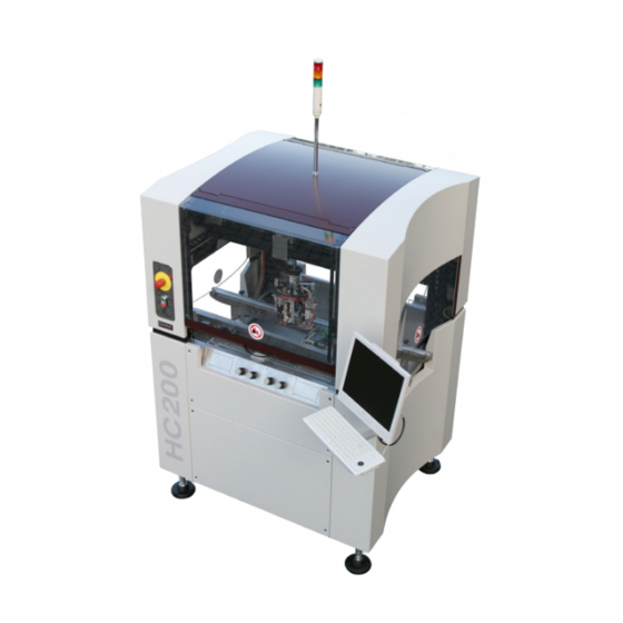
HC-100/200
Service Manual Ver1.1
This document contains proprietary information which is protected by copyright. All rights are
reserved. No parts of this document may be photocopied, reproduced, or translated into
another language without the prior written consent of DIMA Group B.V. .
The information contained in this document is subject to change without prior notice.
© Copyright 2008 DIMA Group B.V.
TB-1026
Advertisement
Table of Contents

Related Manuals for DIMA HC-100

Summary of Contents for DIMA HC-100
- Page 1 This document contains proprietary information which is protected by copyright. All rights are reserved. No parts of this document may be photocopied, reproduced, or translated into another language without the prior written consent of DIMA Group B.V. . The information contained in this document is subject to change without prior notice.
-
Page 3: Table Of Contents
Electrical Compartment in Front Electrical Compartment in Rear Detection of Exhausted Air X and Y Movement Head with Connection PCB 3.10 Dispense Head PCB 3.11 Z Movement at HC-100 3.12 ZØ Movement at HC-200 3.13 Embedded Software 3.14 Additional Revision Information 3.14.1 General 3.14.2... - Page 4 Adjusting the Limits for the X Axis 9.9.2 Adjusting the Limits for the Y Axis 9.9.3 Adjusting the Limits for the Z Axis with the HC-100 9.9.4 Adjusting the Limits for the Z Axis with the HC-200 9.9.5 Adjusting the Limits for the Ø Axis with the HC-200...
- Page 5 HYBRID Coater Service Manual ver?1.1 Table of Contents 9.10 Replacing the Differential Pressure Switch 9.11 Fitting a new stop pin in a conveyor Spare Parts Electrical Wiring Diagrams Revision 1.0 Electrical Wiring Diagrams Revision 1.1 Electrical Wiring Diagrams of Options EL-04806 Dispense Head PCB Overview EL-04873 Control PCB Overview EL-04875 Connection PCB Overview...
-
Page 6: Introduction
Due to technical innovations and improvements, data in this manual may differ from the machine at hand. DIMA however tries to keep this manual as up to date as possible. Next table shows an overview of the previous and current versions of this manual. -
Page 7: Model Overview
Model Overview The HYBRID C is available in two versions: HC-100: The HC-100 robot is equipped with X, Y, and Z axis. The 3-axis robot can handle up to 4 different tools. Tools can be dispense valves, spray valves, grippers, etc. -
Page 8: Safety
Chapter 2 HYBRID Coater Servicce Manual ver1.1 Safety Refer to the User Manual for general Safety Information. Warnings Never enter the machine when the motors of the Coating Head or of the Conveyor are running. Do not overrule the hood locks and do not run the HYBRID C in any way with the hoods open. -
Page 9: Machine Overview
HYBRID Coater Service Manual ver1.1 Chapter 3 Machine Overview Introduction This Chapter gives an overview of the machine. Drawings of electrical wiring can be found in Appendix A and B. Electrical Block Diagram Below figure shows the block diagram of the electrical parts of the machine. Cable Z-Limit Chain... -
Page 10: Block Diagram Of Air
Chapter 3 HYBRID Coater Service Manual ver1.1 Block Diagram of Air Below figure shows the block diagram of the air parts of the machine. Valves for Atomising Air or Cable Duct other functions EL-04875 Connection Valves for Up/Down/Tilt/Normal Cable Duct Main Air IN Mounting Bracket for up to 8 Pressure Sensors... -
Page 11: Routing Of The Air Lines
HYBRID Coater Service Manual ver1.1 Chapter 3 3.3.1 Routing of the Air Lines NOTE: This section shows the route from the incoming air till the air switch on the Coating Head. The following sections show the routing of the air lines needed with the several options. -
Page 12: Air Lines Routing Of The Options
C From there (#1) the main air pressure is distributed directly to an air switch #4 on the coating head (with HC-100 = figure 3a). Or to the air switch #5 on the fixed part of the coating head (with HC-200 = figure 3b). - Page 13 Chapter 3 C The short end runs to the inlet (#9) on the back of the solenoid valve (#11). rear of coating head on HC-100 rear of coating had on HC-200 D The outlet (#10) of this solenoid valve (#11) is connected via one of the air lines in the fixed duct and the flexible duct all the way to the first interconnection (#12) on the coating head.
-
Page 14: With Options Hc-1000, Hc-1010, Or Hc-1030
With Options HC-1000, HC-1010, or HC-1030 A At the HC-100 the air line is continued at the underside of the switch (#4) into the flexible air duct. And from there to the inlet connection (#13) of the air block (#14). The air block is used to distribute the pressure of the main air to the various solenoid valves #15 which are mounted on it. - Page 15 HYBRID Coater Service Manual ver1.1 Chapter 3 B At the HC-200 the pressure of the main air is from the air switch #5 through a line into the flexible duct #18 around the Coating Head to the distributing cross #19 under the clear plastic disc.
-
Page 16: With Options Hc-1160/1170
Chapter 3 HYBRID Coater Service Manual ver1.1 With Options HC-1160/1170 The HC-1160 consists of a chain conveyor with two stepper motors, two stopper pin cylinders and one product sensor. The HC-1170 has additionally two clamping rails which are actuated by two air cylinders. The next block diagram shows the lay-out of the connections. -
Page 17: Electrical Compartment In Front
HYBRID Coater Service Manual ver1.1 Chapter 3 = Electrical Wires Electrical Compartment in Front This compartment contains: Opening through which the hose for external air supply enters the machine. This hose is connected to a pressure controller and air filter/ water separator unit. ... - Page 18 Chapter 3 HYBRID Coater Service Manual ver1.1 Pos. Cable Purpose Remark KHP-0100-0501 mains of PC EL-04763 keyboard EL-04763 track ball EL-04766 (RS232) software interface P11 on main board EL-04772 display EL-04780 (USB) software interface P13 on main board for option control via connector bracket for option control via connector bracket...
-
Page 19: Electrical Compartment In Rear
HYBRID Coater Service Manual ver1.1 Chapter 3 Electrical Compartment in Rear This compartment contains: Electro panel with EL-04873 Control PCB and EL-04872 Advanced Power LED Control (See wiring diagrams HC-0200-0315 and HC-0200-0415). Mounting bracket for external connections (Ethernet, USB etc.). The EL-04873 Control PCB contains the complete control of the machine. - Page 20 Chapter 3 HYBRID Coater Service Manual ver1.1 Appendix I shows more detailed information about the I/O of this PCB. For spare parts of this part see wiring diagrams. Mounting bracket for external connections (Ethernet, optional SMEMA, weighing scale, etc.).
-
Page 21: Detection Of Exhausted Air
X movement vane switches are present at the head. Also here guarding of the position system is present. See wiring diagram HC-0200-0002 for more information. Spare parts: EL-07164 Vane switch of photo interrupter OPB815W HC-100-SS-53 Stepper motor SECM-268-E3.0A with connector... -
Page 22: Head With Connection Pcb
PCB. On the head also the stepper motors for Z and Ø are located. NOTE: IN CASE OF A HC-100 NO Ø STEPPER MOTOR, VANE SWITCH OR ENCODER ARE PRESENT! On the bottom side of the Connection PCB a number of flat cable connectors are present. -
Page 23: Dispense Head Pcb
Z Movement at HC-100 In case of a HC-100 a stepper motor is used which is connected via a coupling to a spindle. One revolution of the spindle gives a movement of 8mm. A sensor is used for the upper detection of the Z. -
Page 24: Zø Movement At
* 25 = 7.639mm. Spare parts: EL-02527 Inductive proximity switch M8 EL-07164 Vane switch of photo interrupter OPB815W EL-07183 Three channel encoder module HC-200-SS-80 Encoder disc 2” 2500lines with Index HC-100-SS-53 Stepper motor SECM-268-E3.0A with connector... -
Page 25: Embedded Software
General The machine with serial number 601200600005 is equipped with the HC-100-SS-50 stepper motors for the X, Y, Z, and Φ instead of the HC-100-SS-53. When replacement is required, use the HC-100-SS-53. The machines with serial number 601200600002 till 601200600004, 600200700001, and 600200700002 are equipped with the HC-100-SS-50 stepper motors for the Z and Φ... -
Page 26: Specific
600200700002 have an electro panel according the revision 1.0 drawings with a control circuit working on 230 VAC instead of 24VAC as all other machines have. 3.14.2 HC-100 Specific All HC-100 machines (except 600200700002) are equipped with the EL-04879 Dispense Head PCB. Machine 600200700002 has a wired solution. 3.14.3 HC-200 Specific Machines with serial number 601200600002 –... -
Page 27: Machine Installation
HYBRID Coater Service Manual ver1.1 Chapter 4 Machine Installation Pre-installation Checks Some time before installation of the machine, the customer will have received the Installation Protocol. This protocol describes the requirements of the installation site. To make sure that the site is well prepared, the following items should be checked before installation: ... - Page 28 Chapter 4 HYBRID Coater Service Manual ver1.1 There are two versions which are explained next: Old version: Front covers Attachment bolts (4x) New version: attachment to pallet is the same as previous Front covers...
-
Page 29: Placing And Leveling The Machine
HYBRID Coater Service Manual ver1.1 Chapter 4 Placing and Leveling the Machine Place the machine on a position as described in the User Manual. To level a stand-alone machine: Adjust the height of the adjustable feet to get the mounting table to the desired height. ... -
Page 30: Completion Of The Installation
Installing Options DD-52XX This means installing the option DD-52XX to the HYBRID. This means that the option HC- 1980 is installed to the HC-100 or that the option HC-1390 is installed to the HC-200, see also Section 4.7. In order to install option DD-52XX to a HC-200, it is sufficient to connect the wires according to Module drawing DD-52XX (Additional Valve Heating), see Appendix C. - Page 31 HYBRID Coater Service Manual ver1.1 Chapter 4 3. Mount the Solenoid Valve with the bracket at the rear in the next free position. If there is a free spot on an already placed bracket, you can remove the valve from its bracket and mount in on that bracket.
- Page 32 Chapter 4 HYBRID Coater Service Manual ver1.1 7. Connect the electric wires of the Solenoid Valve to the connector second from the left on the bottom of the large PCB. Now all is connected. 8. What is left are the software settings: 9.
-
Page 33: Installing Option Hc-1210/ Hc-1215
HYBRID Coater Service Manual ver1.1 Chapter 4 4.6.3 Installing Option HC-1210/ HC-1215 This means installing the HC-1210 and/or HC-1215 Cartridge Retainers in the working area of the machine. Preferably install these cartridge retainers in the right rear of the working area so the coating head doesn’t interfere with the cartridges. -
Page 34: Installing Options Hc-1235 And Hc-1236
Chapter 4 HYBRID Coater Service Manual ver1.1 connection IN = air Connection OUT = fluid 4.6.5 Installing Options HC-1235 and HC-1236 This means installing the HC-1235 or HC-1236 (stainless) Steel Tank outside the HYBRID and connecting it to the HYBRID. The connection of the HC-1235 or HC-1236 is essentially the same as the smaller tanks. - Page 35 D25 connector see Appendix I for I/O Assignment. B With the HC-100 the wires of the sensor (#3) have to be connected to the corresponding D25 connector as follows: Here the wires (#5, 6, and 7) have to be connected to the next free pins in this D25 connector according to the following example.
-
Page 36: Installing Options Hc-1380 And Hc-1390
Installing Options HC-1380 and HC-1390 The preparation for valve heating HC-1380 and HC-1390 are of similar layout. The only difference is that the HC-1380 is designed for the HC-100 and the HC-1390 is designed for the HC-200. For the HC-200 a different Flexible Cable Duct is needed, the HC-100-SS-51 has to be... -
Page 37: Installing Options Hc-1160 And Hc-1170
HC-1170 is a belt conveyor with clamping. With the HC- 1160 chain conveyor the chain tension is set at the DIMA factory. When the chain needs to be tensioned; don’t adjust is too tight! With the HC-1170 belt conveyor the belt tension is set at the DIMA factory. - Page 38 Chapter 4 HYBRID Coater Service Manual ver1.1 overdrive function in the software which can ensure that a product definitely reaches the stopper pins. When speed is high and/or weight of the product is high, it may be necessary that the product is stopped earlier and therefore the product detect sensor can be moved further away from the stopper pins.
-
Page 39: Adjusting The Conveyor Level And Height
4.8.2 Adjusting the Conveyor Level and Height When present on a HC-100 or HC-200 the conveyor of either type HC-1160 or HC-1170 are already adjusted to the correct height and level at the DIMA factory. Later on when adjusting the height and level of the conveyor is necessary, the procedure for both the HC-1160 and the HC-1170 is done in the same way. -
Page 40: Setting-Up The Weight Scales
Chapter 4 HYBRID Coater Service Manual ver1.1 D After this the units have to be recalibrated; so recalibrate the ‘Applicator height’, the ‘Product Level’ and ‘Move Height’ for each of the units 1 till 4 (when mounted). Setting-up the weight scales Two different weight scales may be connected to the your HybridC. - Page 41 HYBRID Coater Service Manual ver1.1 Chapter 4 the display. Through the button you get into the menu and through the levels of the menu.
- Page 42 Chapter 4 HYBRID Coater Service Manual ver1.1 At a 83N scale: following figure shows the entry sequence on the LCD display. NOTE: when Ver1.2 or later of the PC software is installed, the PC configuration settings are automatically adopted as set in the Device Manager/ Port Settings of the specified communication port.
-
Page 43: Maintenance
Diagnostics contains very useful information about machine performance and can be used to determine if regular maintenance will be due. After each service visit, the diagnostics data should be saved to a file and send to DIMA (to service@dimagrp.com). For easy identification, the file name is given automatically by the... -
Page 44: Regular Maintenance
HYBRID Coater Service Manual ver1.1 Regular Maintenance DIMA advises her customers to have a DIMA authorized service engineer to check the HYBRID once every half year, to perform maintenance according to the following 2-year maintenance cycle, see checklist further in this section. The following items correspond with the numbers in the checklist. - Page 45 HYBRID Coater Service Manual ver1.1 Chapter 5 10 Check all cables and air lines in cable ducts : Check all cables and air lines in the cable ducts for damage, especially at the points where these bend a lot and at the entrance points. 11 Draining EP Differential Pressure Switch : ...
- Page 46 17 Lubrication of Z drive bearing (IKO TU40); nipples on runners (on HC-100) : Use grease: Shell Alvania EP2 ...
- Page 47 HYBRID Coater Service Manual ver1.1 Chapter 5 23 Machine calibration : Refer to User Manual of the Hybrid C: You can choose between a full calibration and a limited calibration (check the box!). A full calibration is needed ...
-
Page 48: Checklist For The Maintenance Of The Hybrid
Detail of each item is given in the previous Chapter. ATTENTION: copy this list for each service of the HYBRID and return it to DIMA. NOTE: Frequency to perform this service per two years: digit 4 means once every half a year, digit 2 means once a year and digit 1 means once every two years. - Page 49 HYBRID Coater Service Manual ver1.1 Chapter 5 Actions to be performed Frequency Done years 11 Draining EP Differential Pressure Switch Remarks: 12 Check exhaust system Remarks: 13 Lubrication of X and Y drive bearing nipples on runners Remarks: 14 Lubrication of X and Y drive bearing spindles Remarks: 15 Lubrication of Y guide bearing nipples on runners Remarks:...
- Page 50 Chapter 5 HYBRID Coater Service Manual ver1.1 Actions to be performed Frequency Done years 23 Machine calibration Remarks: 24 Check positions of units/ syringes Remarks: 25 Perform an overall function test Remarks: Machine type and serial nr. :____________________________________________ Customer Name :____________________________________________ Actions performed by :____________________________________________...
- Page 51 HYBRID Coater Service Manual ver1.1 Chapter 5 Used Parts: Part number Description Amount...
-
Page 52: Electrical Wiring
Appendix A shows the wiring diagrams of the electro panel with Revision 1.0. Other wiring diagrams match with Revision 1.1. Appendix B shows the wiring diagrams with Revision 1.1. Serial numbers HC-100 Revision Connection Dispense Head ... - Page 53 : Sub Frame MHC-0200-0007 : Head HC-100 MHC-0200-0107 : Head HC-100 Connection PCB MHC-0200-0207 : Head HC-100 Dispense Head PCB MHC-0200-0008 : Head HC-200 MHC-0200-0108 : Head HC-200 Connection PCB MHC-0200-0208 : Head HC-200 Dispense Head PCB ...
-
Page 54: Pneumatics
HYBRID Coater Service Manual ver1.1 Pneumatics Overview Spare parts: these are shown in Chapter 10 Pneumatics Diagram This section contains the following pneumatics diagrams: PHC-100 sheet 1 : Pneumatics diagram HC-100 PHC-200 sheet 1 : Pneumatics diagram HC-200... - Page 55 HYBRID Coater Service Manual ver1.1 Chapter 7...
- Page 56 Chapter 7 HYBRID Coater Service Manual ver1.1...
-
Page 57: Diagnostics For Pcb's
HYBRID Coater Service Manual ver1.1 Chapter 8 Diagnostics for PCB’s Introduction Some PCB’s in de HYBRID C are equipped with LED’s to indicate if signals are active or not active. This Chapter shows the meaning of those LED’s. Controller EL-04873 Below figure shows the EL-04873 Controller without the EL-04548 Processor Module and the EL-04874 Stepper Driver Modules. -
Page 58: Led's On Upper Left Side Of The El-04873
Chapter 8 HYBRID Coater Service Manual ver1.1 8.2.1 LED’s on Upper Left Side of the EL-04873 Used for State 24Volt indication Must be ON! Otherwise check fuses and power. This 24Volt is used for all inputs and outputs of this PCB. -
Page 59: Led's Near Connectors P1 And P2 On The El-04873
HYBRID Coater Service Manual ver1.1 Chapter 8 Used for State Alive ticker embedded This LED always blinks at 10Hz. software Internally used for embedded Normally lit at low intensity. software USB transmitter This LED is active when USB is transmitting data to the PC. -
Page 60: Led's Near Connector P3 And P4 On The El-04873
Chapter 8 HYBRID Coater Service Manual ver1.1 Used for State Input for ‘Up 1’ till ‘Up 4’ On = Sensor for upper limit detection of the extend till of unit 1-4 is active (up). Off = Sensor for upper limit detection of the extend of unit 1-4 is not active. -
Page 61: Led's On Upper Right Side Of The El-04873
HYBRID Coater Service Manual ver1.1 Chapter 8 Used for State Off = Vane is interrupted (head in right X limit). Input for left limit of Y movement On = Vane is not interrupted (head not in front Y limit). Off = Vane is interrupted (head in front Y limit). Input right limit... - Page 62 Chapter 8 HYBRID Coater Service Manual ver1.1 Used for State Off = Coil of door lock front not activated (FREE). Output door lock back LOCK On = Coil of door lock rear activated (LOCK). Off = Coil of door lock rear not activated (FREE). Input CLOSED of door lock front On = Door lock front closed.
-
Page 63: Led's On Bottom Left Side Of The El-04873
HYBRID Coater Service Manual ver1.1 Chapter 8 Used for State Input is not used at this moment. NPN input for product sensor 2 On = Product sensor 2 detects a product. Off = Product sensor 2 doesn’t detect a product. Input is not used at this moment. -
Page 64: Led's Near Connectors P21 Till P26 On The El-04873
Chapter 8 HYBRID Coater Service Manual ver1.1 Used for State Off = Busy (output contact open). Output SMEMA OUT On = Board available (output contact closed). Off = No board available (output contact open). Input SMEMA IN On = Board available (input sees closed contact). Off = No board available (input sees open contact). -
Page 65: Led's Near Connectors P27 Till P29 On The El-04873
HYBRID Coater Service Manual ver1.1 Chapter 8 Used for State D106 8.2.7 LED’s near Connectors P27 till P29 on the EL-04873 Used for State D107 Input alignment sensor 1 Input is not used at this moment. D108 Input alignment sensor 2 Input is not used at this moment. -
Page 66: Explanation Of Dip-Switches On El-04873
Chapter 8 HYBRID Coater Service Manual ver1.1 Used for State D116 Input LOCKED of door lock 3 On = Door lock 3 locked. Off = Door lock 3 not locked. Input is not used at this moment. D117 Input CLOSED of door lock 4 On = Door lock 4 closed. - Page 67 HYBRID Coater Service Manual ver1.1 Chapter 8 SW2 and SW3 DIP-switches on SW 2 HC-100 HC-200 HC-1100 (static product holder) HC-1150 (non-toothed belt) HC-1150 (toothed belt) HC-1160 (chain) HC-1170 (non-toothed belt with clamping) HC-1170 (belt with clamping) DIP-switches on SW 3...
-
Page 68: Advanced Power Led Controller El-04872
Chapter 8 HYBRID Coater Service Manual ver1.1 Advanced Power LED Controller EL-04872 One of these PCB’s is present on the machine with bright light upgrade. This PCB is located to the left of the large EL-04873 Controller. This PCB refers to the illumination of the camera. Used for State 24 Volt Indication... -
Page 69: Stepper Drivers El-04874
HYBRID Coater Service Manual ver1.1 Chapter 8 Stepper Drivers EL-04874 Up to six of these PCB’s are located on the EL-04873 Controller. They are mounted on hexagon studs. Used for State 48Volt indication Must be On! Otherwise check fuses and power. -
Page 70: Interconnection Pcb El-04875
Chapter 8 HYBRID Coater Service Manual ver1.1 Interconnection PCB EL-04875 This PCB is located at the rear of the head of the machine. - Page 71 HYBRID Coater Service Manual ver1.1 Chapter 8 Used for State Encoder A-channel The LED indicates the state of the A-channel of the Ø encoder. During rotation this LED will go On and Off at a frequency which depends on the rotational speed. Encoder B-channel The LED indicates the state of the B-channel of the Ø...
-
Page 72: Small Repairs And Adjustments
Knob on top of pressure regulator/ filter unit in the left front of the bottom compartment Focusing the Fiducial Camera Focusing the fiducial cameras of the HC-100 and HC-200 require a different focusing height, see next table. NOTE: Before taking on this focusing job it is better to remove all the tools together with its wires and air lines from the Coating Head. -
Page 73: Replacing The Fiducial Camera At A
HYBRID Coater Service Manual ver1.1 Chapter 9 Replacing the Fiducial Camera at a HC-100 NOTE: In order to be able to dismantle the fiducial camera it is better to remove all the tools. A Remove the cover (#1) of the camera. -
Page 74: Replacing The Fiducial Camera At A
Chapter 9 HYBRID Coater Service Manual ver1.1 E Hold the camera (#5) from underneath and slide back the wires together with both connectors. F Now you can lower the camera. G Mount a new camera in the reverse order and pay attention that the camera is mounted so that the connector on top of it is in front and square to the housing. -
Page 75: Replacing Stepper Motors
X, Y, Z, and Ø axis. The procedure for replacing the stepper motors of the X, Y, and Z axis on the HC-100 and replacing the stepper motors of the X and Y axis of the HC-200 are the same. The stepper motors on the HC-200 for the Z and Ø axis have a different construction. -
Page 76: Replacing The Stepper Motor Of The Z Axis On The
Chapter 9 HYBRID Coater Service Manual ver1.1 C Mount the coupling (#4) together with the bushing (#10) to the new stepper motor. Tighten both set screws (#12) Mount the two guide pins (#10 = special tool) into the two bolts (#11) with thread that keep the rubber middle piece (#7) in place. Now you can guide the new motor over the guide pins (#10) and mount and tighten the other screws (#8) back. - Page 77 HYBRID Coater Service Manual ver1.1 Chapter 9 C Then undo the four lower bolts (#6) on the adjusting plate (#7) of the stepper motor (#5). Slide the stepper motor inwards. This way the tension of the toothed belt on the under side is lessened and now you can take the toothed belt of the drive wheel of the stepper motor.
-
Page 78: Replacing The Stepper Motor Of The Ø Axis
Chapter 9 HYBRID Coater Service Manual ver1.1 9.5.3 Replacing the Stepper Motor of the Ø axis The stepper motor for the Ø axis is the upper motor on the coating head of the HC-200. In order to be able to get near this stepper motor, the Coating Head has to be moved all the way to the left hand side of the working area (seen from the front). -
Page 79: Replacing Pcb's Of Stepper Motors
HYBRID Coater Service Manual ver1.1 Chapter 9 Replacing PCB’s of Stepper Motors The PCB’s for the stepper motors are located in the rear of the bottom compartment of the HYBRID on the large PCB. You can identify which PCB corresponds to which stepper motor by the identification of the wires leading to the top of this PCB. - Page 80 Chapter 9 HYBRID Coater Service Manual ver1.1 B Undo the four bolts (#3) on the corners (leave the other two untouched!) and remove the cover (#4) on the side of the upper stepper motor. ATTENTION: Don’t touch the encoder disc; this is a very delicate part! Put a long M3 bolt (approx.
- Page 81 HYBRID Coater Service Manual ver1.1 Chapter 9 Check that the Index Signal (through LED’s D3 and D6) is found when Tool 1 is pointed towards the front. K Turn the Coating Head on the Index Position and shut off the HYBRID and on again. Push CTRL + Shift + Alt + F10 simultaneously and put the Controller in simulation, next out of simulation and then start again without Full Initialization.
-
Page 82: Exchanging The Flexible Cable Duct On The
Chapter 9 HYBRID Coater Service Manual ver1.1 Exchanging the Flexible Cable Duct on the HC-200 The flexible cable duct runs from the interconnection on the fixed part of the coating head to the rotating coating head. In this cable duct run three thin air lines for atomizing air, one thick air line to the air distribution cross, three flat cables, one camera cable (through a similar hose) and one flat grounding strip. - Page 83 HYBRID Coater Service Manual ver1.1 Chapter 9 9. Loosen the union nut of the camera cable on the fixed head. 10. Loosen the union nut of the camera cable on the rotating head. 11. Loosen the four bolts which hold the cover plate of the grounding strip to the fixed head and remove this.
-
Page 84: Adjusting The X, Y, Z And Ø Limits
Do the same with the rear. 9.9.3 Adjusting the Limits for the Z Axis with the HC-100 Move the Coating Head all the way up by hand against the mechanical stop. Adjust the limit sensor of the Z axis. -
Page 85: Adjusting The Limits For The Z Axis With The
HYBRID Coater Service Manual ver1.1 Chapter 9 LEVEL Check by moving the Z shaft by hand if the single radio button changes into a red vane when this limit is reached. 9.9.4 Adjusting the Limits for the Z Axis with the HC-200 Remove the cover and place back the sensor nut. -
Page 86: Adjusting The Limits For The Ø Axis With The
Chapter 9 HYBRID Coater Service Manual ver1.1 9.9.5 Adjusting the Limits for the Ø Axis with the HC-200 Remove the cover and remount the sensor nut. Move the Coating Head all the way counterclockwise by hand and check if the single radio button changes into a red vane when the limit is reached. - Page 87 HYBRID Coater Service Manual ver1.1 Chapter 9 2. Mount the new differential pressure switch on the panel. Remove the cover as shown under item 1. Put the cable through the union nut and connect the wires as follows. The yellow-green cable to ground. Black cable #1 to the upper connection (COMMON). The black cable #2 tot the middle connection (NORM OPEN).
-
Page 88: Fitting A New Stop Pin In A Conveyor
The first generation of stop pins were bolted. The new generation has a press fitting. HC-1160: here the stop pin - HC-100-2021 must be press fitted into the stop block -HC-100- 0521 (twice the same for left and right hand side rail). -
Page 89: 10.Spare Parts
HYBRID Coater Service Manual ver1.1 Chapter 10 10.Spare Parts The following spare parts are available for the HYBRID C. HC-100/HC-200 Common Parts Part No. Description BM-3022 Gas spring BM-9038 Exhaust hose EL-00142 Fuse 5x20mm 2A-F EL-00149 Fuse 5x20mm 2A-T EL-00150... - Page 90 Trackball EL-04807 Camera Illumination (new) EL-04870 Camera Illumination (old) EL-04872 Advanced power LED controller EL-04873 I/O Controller module EL-04874 PCB Stepper driver for X, Y, Z, Phi, transport EL-04875 Interconnect PCB EL-07164 Vane switch HC-100-0324 Spring for guiding material hose...
- Page 91 HYBRID Coater Service Manual ver1.1 Chapter 10 HC-100-SS-34 Calibrating plate HC-100-SS-53 XY Stepper motor. For HC-200 also for Z and Phi HC-100-SS-58 Coupling set between stepper motor and spindle (X and Y motor) KS-0013 O-ring for mounting valve assembly at head...
- Page 92 Alvania EP-2 grease for bearings VP-0089 Adapter for high pressure grease pump VP-0091 High pressure grease pump HC-100 Specific Part No. Description EL-00578 Camera EL-00585 Lens camera EL-04879 PCB Dispense Head HC-100 HC-100-2407 Diaphragm HC-100-SS-54 Z stepper motor HS-100-2508 Diffuser...
- Page 93 Three channel encoder module (in combination with the HC-200-SS-80) HC-200-SS-80 Encoder disk 2” 2500 lines with index (in combination with the EL- 07183) HC-100-4808 Closing plate for placement when HC-1000 / HC-1010 is removed HC-100-SS-51 Flexible cable duct ( please contact DIMA before ordering)
- Page 94 Chapter 10 HYBRID Coater Service Manual ver1.1 HC-100-SS-55 Head Cable assembly with heating (please contact DIMA before ordering) HS-100-2708 Diffuser PP-1000-4810 Diaphragm EL-04876 PCB Dispense Head HC-200 HC-1000 Part No. Description HC-100-SS-60 Dispense valve mounting plate PN-2103 Manifold gasket for use with PN-...
- Page 95 HYBRID Coater Service Manual ver1.1 Chapter 10 PN-5015 Valve 5/2 (wide type used at older version) PN-5024 Valve for moving Z slide PN-9084 Z-slide HC-1010 Part No. Description HC-100-1722 Z-slide for HC-1010...
- Page 96 Chapter 10 HYBRID Coater Service Manual ver1.1 HC-100-SS-59 Spare tilt replacement set PN-2031 Pneumatic fitting male elbow 04-M5 PN-2032 Pneumatic speed controller 04-M5 PN-2103 Manifold gasket for use with PN- 5024...
- Page 97 HYBRID Coater Service Manual ver1.1 Chapter 10 PN-2104 Pneumatic valve mounting screw for use with PN-5024 PN-5015 Valve 5/2 (wide type used at older version) PN-5024 Valve for moving Z slide PN-5032 Valve 5/2 (wide version with extra thread for old units)
- Page 98 Chapter 10 HYBRID Coater Service Manual ver1.1 PN-9008 Sensor for tilt cylinder HC-1020 Part No. Description AM-5061 Bearing HC-1020-0001 Spring 25mm HC-1030 Part. No. Description HC-100-SS-60 Dispense valve mounting plate PN-2103 Manifold gasket for use with PN- 5024...
- Page 99 HYBRID Coater Service Manual ver1.1 Chapter 10 PN-2104 Pneumatic valve mounting screw for use with PN-5024 PN-5024 Valve for moving Z slide PN-9084 Z-slide HC-1050 Part No. Description EL-07165 Pressure sensor 0-7 Bar...
- Page 100 Chapter 10 HYBRID Coater Service Manual ver1.1 PN-4064 Pressure regulator 0-8 Bar PN-5031 5/2 Valve for switching low pressure HC-1051 Part No. Description EL-07166 Pressure sensor 0-2.5 Bar PN-4056 Pressure regulator 0-2.5 Bar...
- Page 101 HYBRID Coater Service Manual ver1.1 Chapter 10 PN-5031 5/2 Valve for switching low pressure HC-1160 Part No. Description AM-1061 Chain HC-100-SS-50 Stepper motor transport HC-100-SS-61 Chain wheel HC-100-SS-62 Chain wheel for mounting at stepper motor...
- Page 102 Chapter 10 HYBRID Coater Service Manual ver1.1 HC-100-SS-69 PCB detect sensor with connector PN-5013 Valve for stop pin (3/2) BM-9055 Hot temperature grease for chain HC-1170 Part No. Description AM-1043 Product Transport belt (2 required per machine) HC-100-2625 Guide bushing for clamp mechanism...
- Page 103 HYBRID Coater Service Manual ver1.1 Chapter 10 HC-100-4025 Guide pin for product (12 required per machine) HC-100-SS-50 Stepper motor transport HC-100-SS-65 Guide wheel HC-100-SS-69 PCB detect sensor with connector...
- Page 104 Chapter 10 HYBRID Coater Service Manual ver1.1 PN-5013 Valve for stop pin (3/2) PN-5015 Valve for PCB clamping (5/2) PN-9063 Cylinder for stop pin PN-9086 Cylinder for PCB clamp...
-
Page 105: Electrical Wiring Diagrams Revision
HYBRID Coater Service Manual ver1.1 Appendix A A. Electrical Wiring Diagrams Revision 1.0 This set of wiring diagrams applies to the HYBRID C machines with serial numbers 600200700001, 600200700002, 601200700001 and 601200600002 till 601200600005. This appendix only contains the wiring diagrams of the electro panel. All other diagrams are equal to the diagrams in Appendix B. - Page 106 Appendix A HYBRID Coater Service Manual ver1.2...
- Page 107 HYBRID Coater Service Manual ver1.1 Appendix A...
- Page 108 Appendix A HYBRID Coater Service Manual ver1.2...
- Page 109 HYBRID Coater Service Manual ver1.1 Appendix A...
- Page 110 Appendix A HYBRID Coater Service Manual ver1.2...
- Page 111 HYBRID Coater Service Manual ver1.1 Appendix A...
-
Page 112: Electrical Wiring Diagrams Revision
Appendix B HYBRID Coater Service Manual ver1.1 B. Electrical Wiring Diagrams Revision 1.1 This set of wiring diagrams applies to the HYBRID C machines. Wiring diagrams of the electro panel do not apply to machines with serial numbers 600200700001, 600200700002, 601200700001 and 601200600002 till 601200600005. - Page 113 HYBRID Coater Service Manual ver1.1 Appendix B...
- Page 114 Appendix B HYBRID Coater Service Manual ver1.1...
- Page 115 HYBRID Coater Service Manual ver1.1 Appendix B...
- Page 116 Appendix B HYBRID Coater Service Manual ver1.1...
- Page 117 HYBRID Coater Service Manual ver1.1 Appendix B...
- Page 118 Appendix B HYBRID Coater Service Manual ver1.1...
- Page 119 HYBRID Coater Service Manual ver1.1 Appendix B...
- Page 120 Appendix B HYBRID Coater Service Manual ver1.1...
- Page 121 HYBRID Coater Service Manual ver1.1 Appendix B...
- Page 122 Appendix B HYBRID Coater Service Manual ver1.1...
- Page 123 HYBRID Coater Service Manual ver1.1 Appendix B...
- Page 124 Appendix B HYBRID Coater Service Manual ver1.1...
- Page 125 HYBRID Coater Service Manual ver1.1 Appendix B...
- Page 126 Appendix B HYBRID Coater Service Manual ver1.1...
- Page 127 HYBRID Coater Service Manual ver1.1 Appendix B...
- Page 128 Appendix B HYBRID Coater Service Manual ver1.1...
- Page 129 HYBRID Coater Service Manual ver1.1 Appendix B...
-
Page 130: Electrical Wiring Diagrams Of Options
HC-1050 = Solenoid Valve of Pressure Reducing Valve HC-1051 = Solenoid Valve of Pressure Reducing Valve HC-1160 = Conveyor HC-1170 = Conveyor (Rev1.0) HC-1170 = Conveyor (Rev 1.1) HC-1380 = HC-100 Preparation for valve heating HC-1390 = HC-200 Preparation for valve heating... - Page 131 HYBRID Coater Service Manual ver1.1 Appendix C Option DD-52XX...
- Page 132 Appendix C HYBRID Coater Service Manual ver1.1 Option HC-1000...
- Page 133 HYBRID Coater Service Manual ver1.1 Appendix C Option HC-1010...
- Page 134 Appendix C HYBRID Coater Service Manual ver1.1 Option HC1030...
- Page 135 HYBRID Coater Service Manual ver1.1 Appendix C Option HC-1050/1051...
- Page 136 Appendix C HYBRID Coater Service Manual ver1.1 Option HC-1160...
- Page 137 HYBRID Coater Service Manual ver1.1 Appendix C Option HC-1170 (Rev1.0)
- Page 138 Appendix C HYBRID Coater Service Manual ver1.1 Option HC-1170 (Rev 1.1)
- Page 139 HYBRID Coater Service Manual ver1.1 Appendix C Option HC-1380...
- Page 140 Appendix C HYBRID Coater Service Manual ver1.1 Option HC-1390...
-
Page 141: El-04806 Dispense Head Pcb Overview
HYBRID Coater Service Manual ver1.1 Appendix D D. EL-04806 Dispense Head PCB Overview This appendix shows more detailed information about the connectors on the outside of the EL-04806 Dispense Head PCB. This PCB is only used in the HC-200. CONNECTOR PINNING Below figure shows the pinning of the connectors which are the counterparts of the connectors present on the PCB. - Page 142 Appendix D HYBRID Coater Service Manual ver1.1 CONNECTOR NUMBERING Below figure shows the position of the connectors on the PCB. Some I/O is dedicated for the machine. Other are present for present and future options. Some of this last I/O is flexible, which means that it can be used as an input which function is determined by the software running on the Personal Computer.
- Page 143 HYBRID Coater Service Manual ver1.1 Appendix D CONNECTOR P4 FOR THE CAMERA This connector is used for connecting the video signal of the camera to the EL-04875 Connection PCB. See wiring diagrams MHC-0200-0108 for more information. CONNECTORS P5 AND P6 FOR DISPENSE MOTORS OR ROTARY VALVES These connectors are present for above mentioned option.
- Page 144 Appendix D HYBRID Coater Service Manual ver1.1 SCHEMATICS OF THE EL-04806 DISPENSE HEAD PCB Below figures show detailed information about the connections between all connectors on this PCB.
-
Page 145: El-04873 Control Pcb Overview
HYBRID Coater Service Manual ver1.1 Appendix E E. EL-04873 Control PCB Overview This appendix shows more detailed information about the connectors on the outside of the EL-04873 Control PCB. CONNECTOR PINNING Below figure shows the pinning of the connectors which are the counterparts of the connectors present on the PCB. - Page 146 The valve mount assemblies are connected to the Dispense Head PCB (EL-04806 or EL- 04876 for HC-200 and EL-04879 for HC-100). Via Connection PCB EL-04875 the limits are connected to the EL-04873 Control PCB. All above limits in the machine are reed contacts...
- Page 147 Connector P2 is connected via cable KHC-0100-0208 to connector P5 of the EL-04875 Connection PCB. See wiring diagram MHC-0200-0315 and MHC-0200-0107 for HC-100 and MHC-0200-0108 for HC-200 for more information. CONNECTOR P3 FOR X, Y, Z AND Ø LIMITS AND Ø ENCODER The connector is used for connecting the signals of the limits of X, Y, Z and Ø.
- Page 148 Control PCB. Connector P3 is connected via cable KHC-0100-0308 to connector P6 of the EL-04875 Connection PCB. See wiring diagram MHC-0200-0315 and MHC-0200-0107 for HC-100 and MHC-0200-0108 for HC-200 for more information. CONNECTORS P4 AND P5 FOR CONVEYOR LIMITS These connectors are not used at this moment. Each connector is used for the connection of...
- Page 149 Connection PCB EL-04875. The dispense motors or rotary valves and illumination are connected to the Dispense Head PCB (EL-04806 or EL-04876 for HC-200 and EL-04879 for HC-100). Connector P14 is the connector on the left side of the Control PCB. It is connected to the EL- 04872 Advanced Power LED Control PCB.
- Page 150 Connector P6 is connected via cable KHC-0100-0408 to connector P7 of the EL-04875 Connection PCB. See wiring diagram MHC-0200-0315 and MHC-0200-0107 for HC-100 and MHC-0200-0108 for HC-200 for more information. CONNECTOR P7 FOR DOORLOCKS 1&2 AND P8 FOR LIGHT TOWER The door locks on the front and back side of the machine are connected to connector P7.
- Page 151 HYBRID Coater Service Manual ver1.1 Appendix E See wiring diagram MHC-0200-0315, MHC-0200-0011, MHC-0200-0018 and MHC-0200- 0028 for more information. CONNECTOR P9 FOR PRODUCT SENSORS These inputs are special because the 24Volt can be switched on-off by software. Also sensors may be used which have a change over contact (PNP and NPN output). On this connector 2 of such sensors can be used.
- Page 152 Appendix E HYBRID Coater Service Manual ver1.1 See wiring diagram MHC-0200-0315 and drawings of the conveyor option for more information. CONNECTORS P17 AND P18 FOR MEDIUM PRESSURE AND AIR Connector P17 and P18 are used to controlling the valves which enable the pressure on the medium or for the atomizing air.
- Page 153 HYBRID Coater Service Manual ver1.1 Appendix E Cables KHC-0100-0111 and KHC-0100-0211 are connected to above connector. The SMEMA connectors on the other side are mounted to the mounting bracket on the backside of the Electrical Compartment. See Appendix C of the machine reference manual for more information.
- Page 154 Appendix E HYBRID Coater Service Manual ver1.1 CONNECTOR P27 FOR ALIGNMENT SENSORS This connector is not used at this moment. CONNECTOR P28 FOR PUSH BUTTONS AND P29 FOR DOOR LOCKS This connector is used to connect the push button on the front control panel of the machine. Connector P29 is not used at this moment.
- Page 155 HYBRID Coater Service Manual ver1.1 Appendix E See wiring diagram MHC-0200-0315 and MHC-0200-0002 for more information. CONNECTORS P30 AND P31 FOR ANALOG I/O Both connectors contain two 0-10Volt outputs and two 0-10Volt inputs. Maximum output current is 5mA. Because both connectors have a identical circuit only the circuit of P30 is shown.
- Page 156 Appendix E HYBRID Coater Service Manual ver1.1 NOTE: IN ABOVE CIRCUIT A 12K RESISTOR IS PRESENT. NEAR THE ANALOGUE TO DIGITAL CONVERTER A RESISTOR OF 10K IS PRESENT TOWARDS GND SO 10.000VOLTS AT THE INPUTS GIVES 10/22*5= 4.545VOLT. CONNECTORS P34 AND P35 FOR TEMPERATURE MEASUREMENT Eight inputs are present for the connection of NTC temperature sensors.
-
Page 157: El-04875 Connection Pcb Overview
HYBRID Coater Service Manual ver1.1 Appendix F EL-04875 Connection PCB Overview This appendix shows more detailed information about the connectors on the outside of the EL-04875 Connection PCB. NOTE: there a two versions with the same part number. The newest version is upwards compatible, which means that the new version can be used instead of the old version and only has additional possibilities. - Page 158 Appendix F HYBRID Coater Service Manual ver1.1 CONNECTOR NUMBERING VERSION 1 (OLD): Below figure shows the position of the connectors on the PCB.
- Page 159 HYBRID Coater Service Manual ver1.1 Appendix F VERSION 2 (NEW): Below figure shows the position of the connectors on the PCB. Some I/O is dedicated for the machine. Other are present for present and future options. Some of this last I/O is flexible, which means that it can be used as an input which function is determined by the software running on the Personal Computer.
- Page 160 CONNECTORS P1, P2 AND P3 TO DISPENSE HEAD PCB’S These connectors are present to connect the signals from the Dispense Head PCB (EL- 04806 or EL-04876 for HC-200 and EL-04879 for HC-100) to the EL-04873 Control PCB. See wiring diagrams MHC-0200-0107 (for HC-100) and MHC-0200-0108 (for HC-200) for more information.
- Page 161 HYBRID Coater Service Manual ver1.1 Appendix F SCHEMATICS OF THE EL-04875 CONNECTION PCB Below figures show detailed information about the connections between all connectors on this PCB.
- Page 162 Appendix F HYBRID Coater Service Manual ver1.1...
-
Page 163: El-04876 Dispense Head Pcb Overview
HYBRID Coater Service Manual ver1.1 Appendix G G. EL-04876 Dispense Head PCB Overview This appendix shows more detailed information about the connectors on the outside of the EL-04876 Dispense Head PCB. This PCB is only used in some HC-200 machines. See Chapter 6 for information regarding these machines. - Page 164 Appendix G HYBRID Coater Service Manual ver1.1 Some I/O is dedicated for the machine. Other are present for present and future options. Some of this last I/O is flexible, which means that it can be used as an input which function is determined by the software running on the Personal Computer.
- Page 165 HYBRID Coater Service Manual ver1.1 Appendix G CONNECTOR P7 FOR EL-04870 ILLUMINATION PCB This Advanced Fiducial Camera Illumination PCB contains LED’s which illuminate the product. See wiring diagrams MHC-0200-0108 for more information. CONNECTOR PAIRS P11 AND P21 FOR VALVE MOUNT ASSEMBLY 1 These connectors are used for the connection of valve mount assembly 1.
- Page 166 Appendix G HYBRID Coater Service Manual ver1.1...
-
Page 167: El-04879 Dispense Head Pcb Overview
H. EL-04879 Dispense Head PCB Overview This appendix shows more detailed information about the connectors on the EL-04879 Dispense Head PCB. This PCB is only used in the HC-100. CONNECTOR PINNING Below figure shows the pinning of the connectors which are the counterparts of the connectors present on the PCB. - Page 168 Appendix H HYBRID Coater Service Manual ver1.1 Some I/O is dedicated for the machine. Other are present for present and future options. Some of this last I/O is flexible, which means that it can be used as an input which function is determined by the software running on the Personal Computer.
- Page 169 HYBRID Coater Service Manual ver1.1 Appendix H SCHEMATICS OF THE EL-04879 DISPENSE HEAD PCB Below figures show detailed information about the connections between all connectors on this PCB.
-
Page 170: I/O Assignment
Appendix I HYBRID Coater Service Manual ver1.1 I/O Assignment This appendix shows more detailed information about assignment of I/O to certain functions of the machine. Paragraph 6 of Chapter 2 of the HYBRID Coater Reference Manual describes how I/O can be defined for use in machine and product scripts. - Page 171 HYBRID Coater Service Manual ver1.1 Appendix I Reference EL-04876 EL-04806 EL-04879 Name Remarks StdSensorIn01 P21 pins 5-6 P21 pins 5-6 P11 pins 11-12 Tilt 1 Valve mount ass.1 StdSensorIn02 P22 pins 5-6 P22 pins 5-6 P12 pins 11-12 Tilt 2 Valve mount ass.2 StdSensorIn03 P23 pins 5-6...
- Page 172 Appendix I HYBRID Coater Service Manual ver1.1 other outputs StdDigitalOut01 StdDigitalOut04 StdDigitalOut15 StdDigitalOut22 are present on the Dispense Head PCB. Reference EL-04876 EL-04806 EL-04879 Name Remarks StdDigitalOut01 n.a. P31 pins 3-6 P11 pins 21-24 Spare Output 1 Valve heating 1 StdDigitalOut02 n.a.
- Page 173 HYBRID Coater Service Manual ver1.1 Appendix I DIGITAL FLOW COUNTERS Four digital inputs are referenced as StdFlowIn01 to StdFlowIn04 which normally have dedicated function but can be used for other purposes. Reference EL-04873 Name Remarks StdFlowIn01 P25 pins 1-4 Flow 1 Switch or 24Volt sensor with PNP or NPN output StdFlowIn02 P25 pins 5-8...
- Page 174 Appendix I HYBRID Coater Service Manual ver1.1 ANALOG PRESSURE IN Seven analog inputs are referenced as StdPressIn01 to StdPressIn07 which normally have dedicated function but can be used for other purposes. The pressure sensors are mounted on a bracket at the right hand side of the EL-04873 Control PCB. Reference EL-04873 Name...
Need help?
Do you have a question about the HC-100 and is the answer not in the manual?
Questions and answers